Mostrar como configurar 3 três o gateway DVW para criar uma rede sem fio que permite a comunicação do CLP da Série AS, IHM DOP-100 e o Computador a longas distâncias conforme mostrada na figura abaixo

Configuração do AS e da DOP-100
Configuração do AS
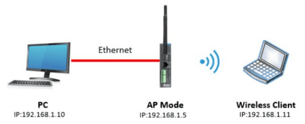
No modo AP, o ponto de acesso serve como ponto intermediário entre dispositivos para conexão com ou sem fio e transmissão de dados.
Procedimentos de configuração
- Defina todos os endereços IP no mesmo segmento. Ou seja, na mesma rede.
- Faça login na página do dispositivo sem fio DVW no PC, o IP padrão é 192.168.1.5. O nome de usuário e a senha padrão são admin/password.

Configuração da DOP-100

Configuração do DVW

Configuração do modo AP (Access Point)
No modo AP, o ponto de acesso serve como ponto intermediário entre dispositivos para conexão com ou sem fio e transmissão de dados.
Procedimentos de configuração
- Defina todos os endereços IP no mesmo segmento. Ou seja, na mesma rede.
- Faça login na página do dispositivo sem fio DVW no PC, o IP padrão é 192.168.1.5. O nome de usuário e a senha padrão são admin/password.

- Em WLAN2.4G listado no menu, selecione Modo de operação, escolha o modo AP e clique em Aplicar.

- Selecione Configuração básica e configure o nome SSID, bem como WPA2-PSK para o modo de segurança (recomendado) e clique em Aplicar.

- Para o cliente (sem fio), procure por DVW SSID (SlimWiFi_5C54) na lista de AP e clique para concluir a transmissão de dados on-line via conexão sem fio. Nome atribuído em SSID será o nome da rede sem fio (WiFi).
- O Teste de PING, mostra que o PC (192.168.1.10) está se comunicando com o Client (192.168.1.11).

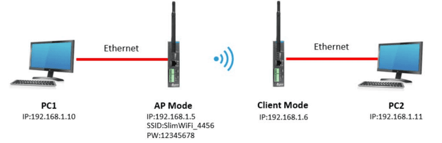
Configuração do modo Client
Os usuários com dois dispositivos DVW, podem utilizar o modo AP em um dispositivo e no outro o modo cliente, ambos são combinados via conexão sem fio. No entanto, apenas a conexão LAN pode ser usada no modo cliente, ou seja, dispositivos ou conexões sem fio não podem ser utilizadas no modo Client.
Procedimentos de configuração
- Defina todos os endereços IP no mesmo segmento.
- Modo AP: Proceder conforme item Configuração do modo AP (Access Point).
- Modo cliente: faça login na página do dispositivo cliente sem fio no PC por meio da configuração IP padrão 192.168.1.6. O nome de usuário e a senha padrão são admin/password.
- Em WLAN2.4G listado no menu, selecione Modo de operação, escolha Modo client e clique em Apply.

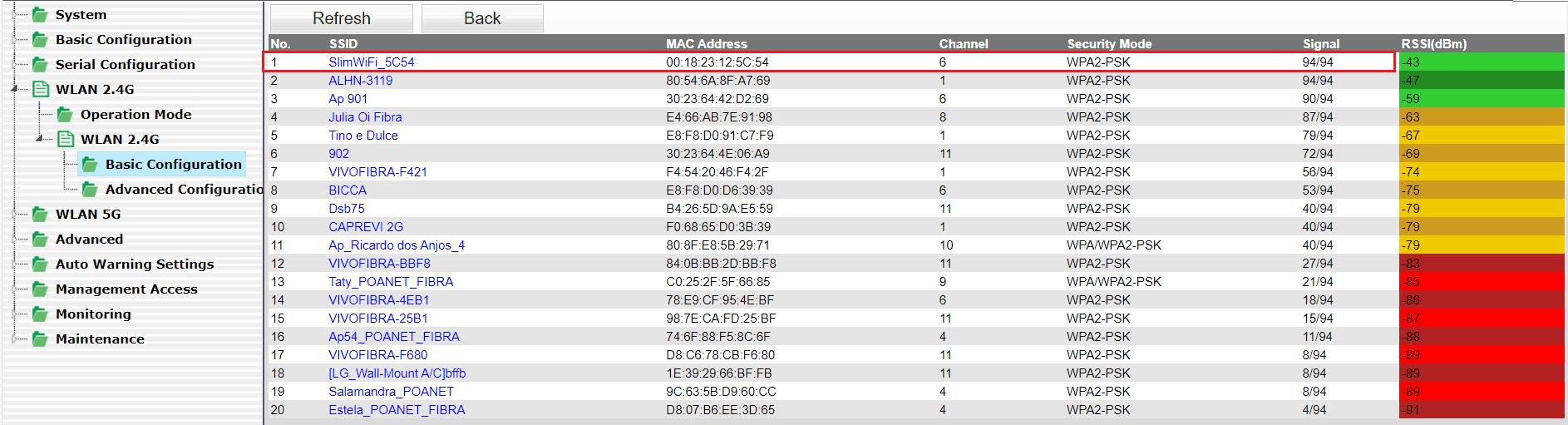
- Selecione Configuração básica e clique em “Site Survey”.

- Selecione o SSID AP configurado (por exemplo, SlimWiFi_5C54). Quando o SSID não puder ser encontrado, clique em “Refresh”.
- Digite a senha para configuração do AP e clique em Apply para concluir a conexão do cliente e do AP

- Quando a conexão estiver concluída, selecione Ping em Maintenance. Em seguida, digite o IP de destino para testar a conexão. Para uma conexão bem-sucedida, o tempo de resposta do AP Ping deve aparecer. (Veja abaixo).

- O teste de PING via terminal do Windows feitos a partir do AP para ver a resposta do Client

Introdução
O ajuste do servo é parte integrante de qualquer sistema de movimento e impacta diretamente a precisão e o desempenho. Um sistema ajustado corretamente pode fornecer maior precisão e mais estabilidade. O nosso servo drive pode ser ajustado seguindo o fluxograma abaixo (Fig. 01). Primeiro, comece com One Touch Tuning. Se você não estiver satisfeito com os resultados do ajuste, use Auto Tuning, Gain Tuning e modo Manual em sequência para atender aos requisitos. Este documento descreverá o processo para fazer o ajuste One Touch tuning e o Auto tuning através do nosso Software ASDA-Soft 6.5.
One Touch Tuning – Durante o processo de ajuste, o motor se move levemente e faz ruído de alta frequência. Para mais informações sobre o procedimento detalhado da operação, consulte a Seção 5.3 do Manual de Usuário.
Auto tuning – Você pode usar a função ajuste automático com ASDA-Soft ou através do painel. A fonte de comando pode ser o servo drive ou o controlador. Durante o processo de ajuste, o drive controla o motor para girar para frente e para trás entre os dois pontos de posicionamento. Para o procedimento detalhado da operação, consulte a Seção 5.4 do Manual de Usuário.

Figura 01 – Diagrama Procedimento de Ajuste
Nota: O diagrama mostra uma ordem para ajustar o sistema, mas não é obrigatório segui-la. Você pode começar o ajuste em qualquer ponto do diagrama (em uma das funções) desde que o resultado seja satisfatório.
Dispositivos, Software e Firmware
| Model | Versão | Documentos Relacionados | |
| ASDA | ASDA-B3A | 2.16 | Delta ASDA-B3 Series Servo Drive User Manual |
| Plataforma de Software | ASDA_SOFT | V6.5.0.0 | |
| https://downloadcenter.deltaww.com/ https://downloadcenter.deltaww.com/en-US/DownloadCenter?v=1&q=asda-soft&sort_expr=cdate&sort_dir=DESC | |||
One Touch Tuning
A função One Touch Tuning funciona com ASDA-Soft. Durante o processo de ajuste, o motor se move e faz ruído de alta frequência. No modo One Touch Tuning, a função de eliminação de vibração é habilitada e a função de supressão de vibração de baixa frequência é desabilitada. Se as duas funções forem habilitadas simultaneamente, a resposta se tornará mais lenta.
A tabela a seguir lista os parâmetros cujas configurações mudam de acordo com os resultados do One Touch Tuning.


Precauções para One Touch Tuning
- O One Touch Tuning NÃO PODE SER FEITO no sistema com parte mecânica que se move apenas em uma única direção.
- O ajuste de um toque NÃO PODE SER USADO CORRETAMENTE nos sistemas onde a relação de inércia de carga (parte mecânica) muda drasticamente ou é maior que 100 vezes a inércia do motor.
- O ajuste de um toque NÃO PODE SER USADO CORRETAMENTE nos sistemas onde o atrito viscoso da parte mecânica é alto.
- O ajuste de um toque NÃO PODE SER USADO CORRETAMENTE nos sistemas onde o limite de torque da parte mecânica é muito baixo.
- O ajuste de um toque NÃO PODE SER USADO CORRETAMENTE nos sistemas onde a folga da engrenagem (gearbox backlash) na parte mecânica é muito grande.
One Touch Tuning com ASDA-Soft
Passo 1 – Inicie o arquivo executável ASDA-Soft V6.5 e a tela será mostrada como na figura 02.

Caso não tenha instalado, acesse o site da Delta para baixar o ASDA-Soft V6.5 gratuitamente. Após instalar o ASDA-Soft V6.5, inicie o arquivo executável e a tela será como na figura 02.

Figura 02 – Tela inicial do ASDA-Soft V6.5
Passo 2 – Certifique-se de que seu servo drive, servo motor e energia estejam todos conectados corretamente. Certifique-se que o Select Device é a série correta do servo drive, clique em Search, e o software seleciona automaticamente a porta de comunicação correspondente (USB Driver for Delta AC Servo Drive). Então, clique em Add para que o ASDA-Soft fique no modo online.

Passo 3 – Quando o ASDA-Soft estiver no modo online, a janela do programa aparecerá como a seguir.

Se tiver alguma indicação de alarme, você deve resolver os alarmes ou dar um reset nos alarmes para prosseguir com ajuste.
Clique em One Touch Tuning na visualização em árvore da Function List.

Clique em Start

Passo 4 – Leia atentamente o conteúdo na janela de aviso e certifique-se de ter verificado todos os itens um por um. Selecione a caixa de seleção I have read the warning above (Eu li o aviso acima) e clique em Yes.

Aguarde enquanto a função é executada

A tela mostra uma tabela comparando os valores dos parâmetros antes e depois do ajuste. Na tela, você pode fazer o ajuste fino do nível de ganho, e os ajustes afetam as configurações de outros parâmetros relevantes.

Clique em Download para concluir o One Touch Tuning.
Nota: se você clicar em Exit sem clicar em Download primeiro, os valores sugeridos estimados pela função de ajuste de um toque não serão gravados no servo drive.
Auto Tuning
A função Auto Tuning permite que o sistema execute estimativas de inércia da máquina em tempo real e baixe os parâmetros otimizados para o servo drive. Você pode iniciar o autoajuste com o ASDASoft (software) ou pelo painel do drive. Abordarmos somente o autoajuste via software.
A tabela a seguir lista os parâmetros que mudam de acordo com os resultados do autoajuste.


Precauções para Auto Tuning
- Configurações recomendadas para Auto Tuning:
- Velocidade de JOG: 500 rpm ou mais.
- Tempo de aceleração de 0 rpm a 3000 rpm ou tempo de desaceleração de 3000 rpm a 0 rpm: dentro de 200 ms.
- Distância de deslocamento: 1 revolução ou mais.
Observação: é aconselhável definir a distância de deslocamento como a distância mínima para o motor acelerar da velocidade zero até a zona de velocidade constante, com a velocidade constante igual à velocidade de jog definida. Se a distância de deslocamento for muito longa, o tempo de estimativa também será maior. Para peças mecânicas com cursos longos, é recomendável definir a distância de deslocamento como a faixa de trabalho para operação.
- O Auto Tuning NÃO PODE SER FEITO em sistemas onde a parte mecânica se move apenas em uma única direção.
- O Auto Tuning NÃO PODE SER FEITO em sistemas onde a velocidade de movimento da parte mecânica é inferior a 200 rpm.
- O Auto Tuning NÃO PODE SER FEITO em sistemas onde o curso efetivo da parte mecânica é menor que a distância percorrida quando o motor gira 0,5 revolução.
- O ajuste automático NÃO PODE SER FEITO CORRETAMENTE em sistemas que a relação de inércia de carga da parte mecânica muda drasticamente ou é maior que 50 vezes a inércia do motor.
- O ajuste automático NÃO PODE SER FEITO CORRETAMENTE em sistemas em que a largura de banda (bandwidth) da parte mecânica é menor que 10 Hz.
- O ajuste automático NÃO PODE SER FEITO CORRETAMENTE em sistemas em que o atrito viscoso da parte mecânica é alto.
- O ajuste automático NÃO PODE SER FEITO CORRETAMENTE em sistemas em que o limite de torque da parte mecânica é muito baixo.
Fluxograma Auto Tuning
A função Auto Tuning ajuda você a encontrar os parâmetros mais adequados para o seu sistema de acordo com as características da máquina

Você pode usar P2.105 e P2.106 para ajustar a rigidez e a resposta no modo Auto Tuning. Veja o fluxograma a seguir.

Auto Tuning com ASDA-Soft
O Auto Tuning pode ser executado através do painel do drive ou via ADSA-Soft. Esse documento aborda a execução do autoajuste apenas pelo software. Caso não tenha instalado o software, veja Passo 1 a 3 no tópico One Touch Tuning com ASDA-Soft.
Quando o ASDA-Soft estiver no modo online, inicie o auto tuning de acordo com os seguintes passos. Vamos descrever o procedimento de auto tuning apenas usando o servo drive.
Passo 1 – Clique em Auto Tuning na visualização em árvore da Lista de funções

Passo 2 – Clique em Drive: Motion Command from Drive para entrar na tela de configuração do perfil de movimento.

Siga estas etapas para definir o curso de funcionamento do motor:
- Defina P2.105 e P2.106 com base na condição da aplicação.
- P2.105: quanto maior o valor de configuração, maior a largura de banda após o ajuste automático, que é aplicável a dispositivos com alta rigidez ou alta resposta. Por outro lado, quanto menor o valor de configuração, menor a largura de banda após o ajuste automático, que é aplicável a dispositivos com estrutura complexa ou baixa rigidez.
- P2.106: quanto menor o valor de configuração, menor o overshoot após o ajuste automático. Mas se o valor de configuração for muito baixo, o tempo de estabilização pode ser muito longo.
O nível de ajuste automático de ganho 1 (P2.105) e o nível de ajuste automático de ganho 2 (P2.106), estão disponíveis apenas para o Auto Tuning. Para mais detalhes, ver tópico 5.4.5 (Parameters related to auto tuning) do manual do ASDA-B3.
- Coloque o sistema no estado Servo ON.
- A velocidade de JOG padrão é 20 rpm e o tempo de aceleração/desaceleração padrão é 200 ms. Para peças mecânicas com cursos limitados, o movimento em baixa velocidade reduz o risco de colisão. É recomendado executar o posicionamento com dois pontos em baixa velocidade. Para peças mecânicas com cursos mais longos ou sem limites, você pode definir a velocidade do movimento mais alta. Após concluir as configurações, clique no botão Download, e então use o botão esquerdo ou botão direito para girar o motor para a posição 1 e posição 2.


- Verifique o tempo de aceleração/desaceleração e a velocidade de JOG novamente. É aconselhável definir a velocidade de JOG para não menos que 500 rpm. Em seguida, clique no botão Download. Após o download ser concluído, clique em Start Moving, e o motor considera a Posição 1 e a Posição 2 como os limites positivo e negativo e começa a girar nas direções para frente e para trás.
- Após concluir as configurações, certifique-se de que não haja pessoal próximo à máquina. Em seguida, clique em Next.
- Se os resultados do ajuste não atenderem aos requisitos, modifique os valores de configuração de P2.105 e P2.106 ou consulte a Seção 5.6 para ajustar manualmente determinados parâmetros e, em seguida, execute o Auto Tuning novamente.

Passo 3 – Aguarde até que a barra de progresso do ajuste atinja 100%, e uma janela com “Auto tuning completed.” apareça como segue. Então clique em OK.

A tela abaixo mostra uma tabela comparando os valores dos parâmetros antes e depois do ajuste.

Clique em Update para concluir o ajuste automático.
Introdução
Normalmente nos deparamos em nosso cotidiano a necessidade de substituir algum equipamento seja ele para manutenção ou upgrade de hardware, para isso devemos fazer o backup do equipamento a ser substituído. E para garantir o funcionamento correto não basta somente fazer o backup do programa, devemos nos atentar com os valores que contém nas Memórias Internas para que o programa volte em seu funcionamento correto. As memórias podem conter valores importante para o funcionamento do programa como receitas, tempos de acionamentos, contagem e etc.
Os usuários podem editar os valores nos dispositivos D/C/T/HC em lote. E os novos valores nestes dispositivos D/C/T/HC podem ser salvo ou baixado no equipamento.
Edit Register Memory
Após criar um novo programa no IPSOFT, podemos clicar no menu PLC depois em Edit Register Memory.

Tela de Edit Register Memory

Os valores nas tabelas da janela Edit Register Memory não são os valores carregados do PLC. São os valores salvos da última vez que foi alterado ou feito update. Se a janela Edit Register Memory no projeto for aberta pela primeira vez,os valores padrão nas tabelas são 0.
 Os valores podem ser editados na célula de um dispositivo, ao clicar na célula do dispositivo desejado e digite o valor desejado.
Transferindo os dados

Para iniciar a transferência com o equipamento clique no botão Transfer como indica a seta conforme a imagem acima. Então a janela de Transfer setup se abrirá.
Tela de Transfer setup

Clique no botão Add para adicionar o range de Registradores que deseja fazer a Leitura ou Escrita.

Adicione os Ranges desejados e habilite as caixas para selecionar os bancos de registradores a serem transferidos.
Escolha a ação desejada em Read From PLC Device Register para fazer a leitura os valores que estão no equipamento ou Write to PLC Device Register para ecrever os valores no equipamento. Confirme no botão Ok.
Salvando a tabela em Arquivo .csv

Os usuários podem exportar os valores da página atual como um arquivo CSV e editar o arquivo CSV através do Microsoft Excel. Para exportar os valores da página atual, clique com o botão direito na página atual, clique em Export no menu da caixa suspensa.
Para abrir uma tabela já existente clique em Import o usuario poderá abrir um arquivo já criado anteriormente.

Selecione em All para salvar todos as Memórias ou Part para selecionar as Memórias que devem ser salvas. Clique no botão OK.
Selecione uma pasta em Salvar em caixa de listagem suspensa na janela Salvar como, digite um nome de arquivo na caixa Nome do arquivo e clique em Salvar.
Conclusão
Esses passos se aplicam os CLP da Delta no Software de programação Delta ISPsoft. Procure o manual do ISPSoft User Manual para encontrar as informações citadas acima.
Introdução
O documento contém 3 passos para configuração de um roteador da família DX Delta, antes de começar a configuração recomendamos que faça o download do Software DIACom(DIADevice está incluso no pacote) no site da deltaww.com na seção download center.
1° Criar o Túnel de Segurança no site


2°Abrir o Software DIA Device com o cabo ethernet conectado na porta Lan:


Em Secure Tunnel escolha a Tunel que criou na Etapa acima:

3°Etapa Abra o Software DIAcom, faça o Login:

No menu do lado direito escolha a conexão que criou na etapa acima no DIAdevice e clique no botão Create Tunnel:

Após conectado será criado uma nova conexão onde pode verificar em seu painel de controle \ Conexões de Rede. No canto inferior do PC estará o ícone do DIACom enquanto estiver conectado


Introdução
O documento contém informações para troca o endereço IP das câmeras DMV. O usuário deve ter instalado em seu Pc o software DMV-VGR.
DeltaViewer
Abra seu Explorador de Arquivos e procure no Pc as pastas conforme a imagem.

Abra o arquivo DeltaViewer.exe

Com a câmera conectada clique em Open
![]()
1° Nos Parameters altere para modo Guru.
2° Selecione a caixa de Opção GEV CurretIPconfiguration Persistent IP
3° Altere para o IP desejado e reinicie a alimentação da câmera
4° Verifique que seu PC esta na mesa faixa do endereço IP da câmera

Conclusão
Esses passos se aplicam para as Câmera DMV Delta. Procure o manual do usuário para encontrar as informações citadas acima
Guia rápido MS300 para utilizar o CLP interno
O objetivo deste documento é efetuar a configuração do inversor de frequência utilizar o CLP interno, utilizando a linha MS300.
Introdução
As linhas de inversores MS300, MH300, C2000, C2000 Plus, entre outros modelos Delta, possuem o CLP interno incorporado ao inversor, muito utilizado em aplicação de pequeno porte que precisão de uma logica de controle para funcionamento, nesta solução não há a necessidade de utilizar um CLP externo, diminuindo o custo do projeto.
Configuração
Segue passos abaixo:
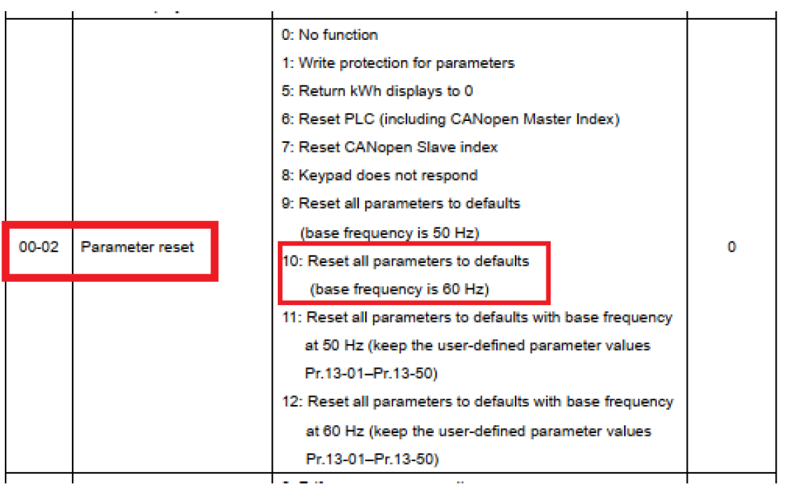
Efetue o “Reset” de fábrica no inversor, caso o CLP interno esteja na opção 1 ou 2 altere para 0:
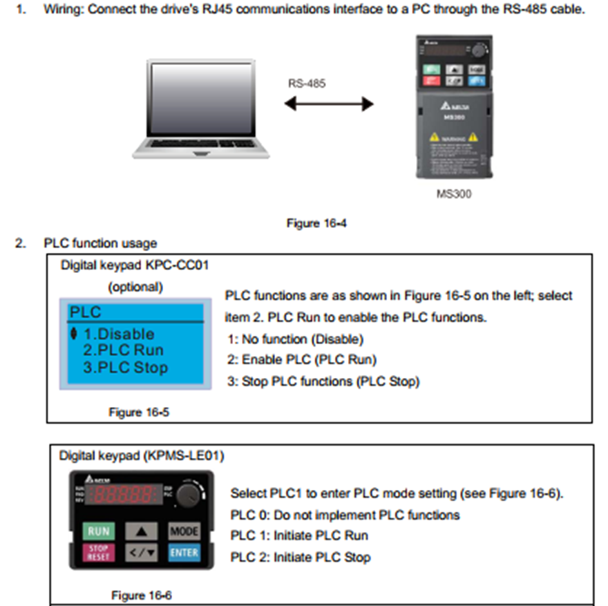
1. Conecte o cabo do computador para o USB do inversor, e selecione o CLP no display do inversor para modo 2:
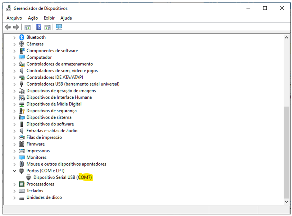
2. Verificar se o computador criou uma porta serial:
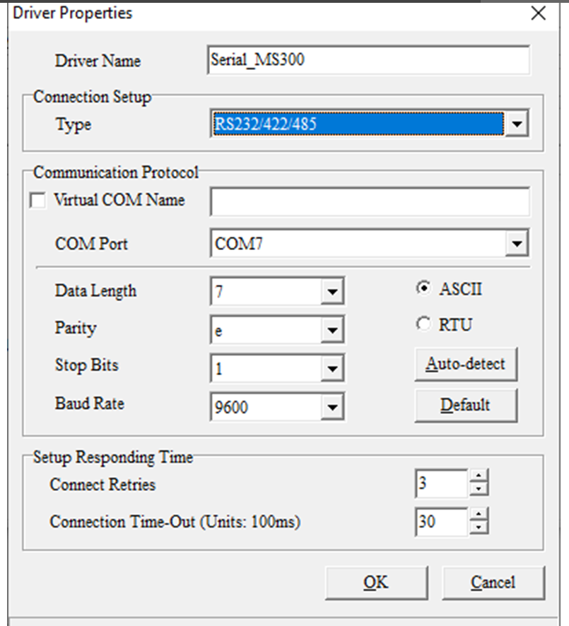
3. Adicionar uma configuração serial ao COMMGR:
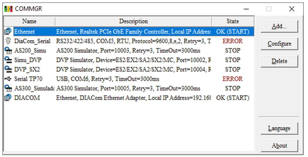
4. Selecionar a porta “COM Port” de acordo com o passo 1:
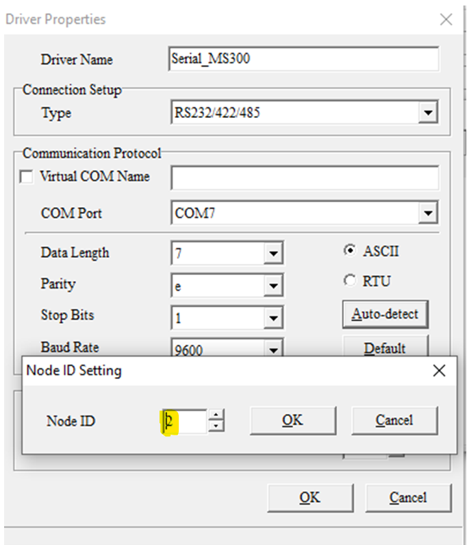
5. Efetuar o Auto Configura no botão “Auto-detect”, altere o ID para 2:
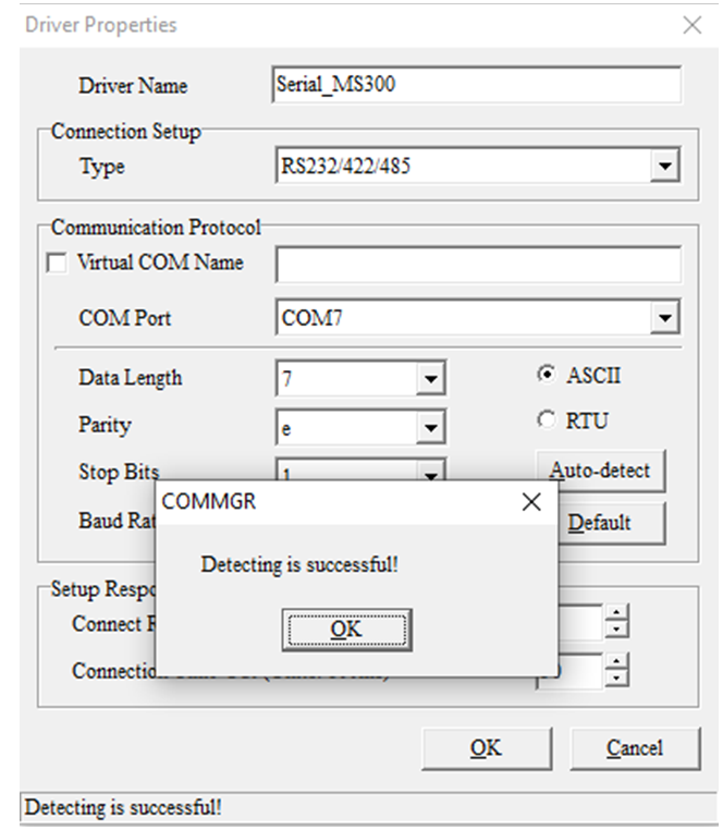
6. Após deve aparecer a mensagem de sucesso:
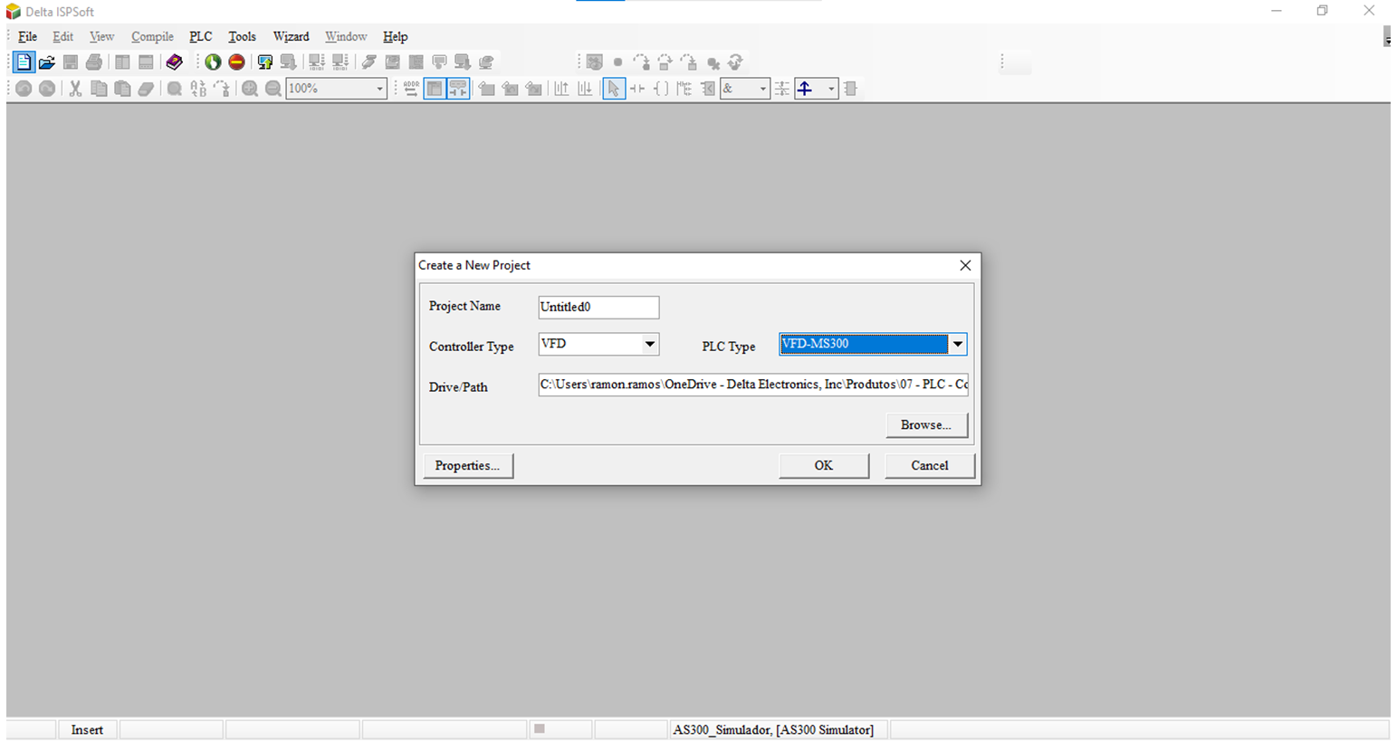
7. Abra o ISPSoft e crie um novo programa selecionando o modelo do CLP como VFD-MS300:
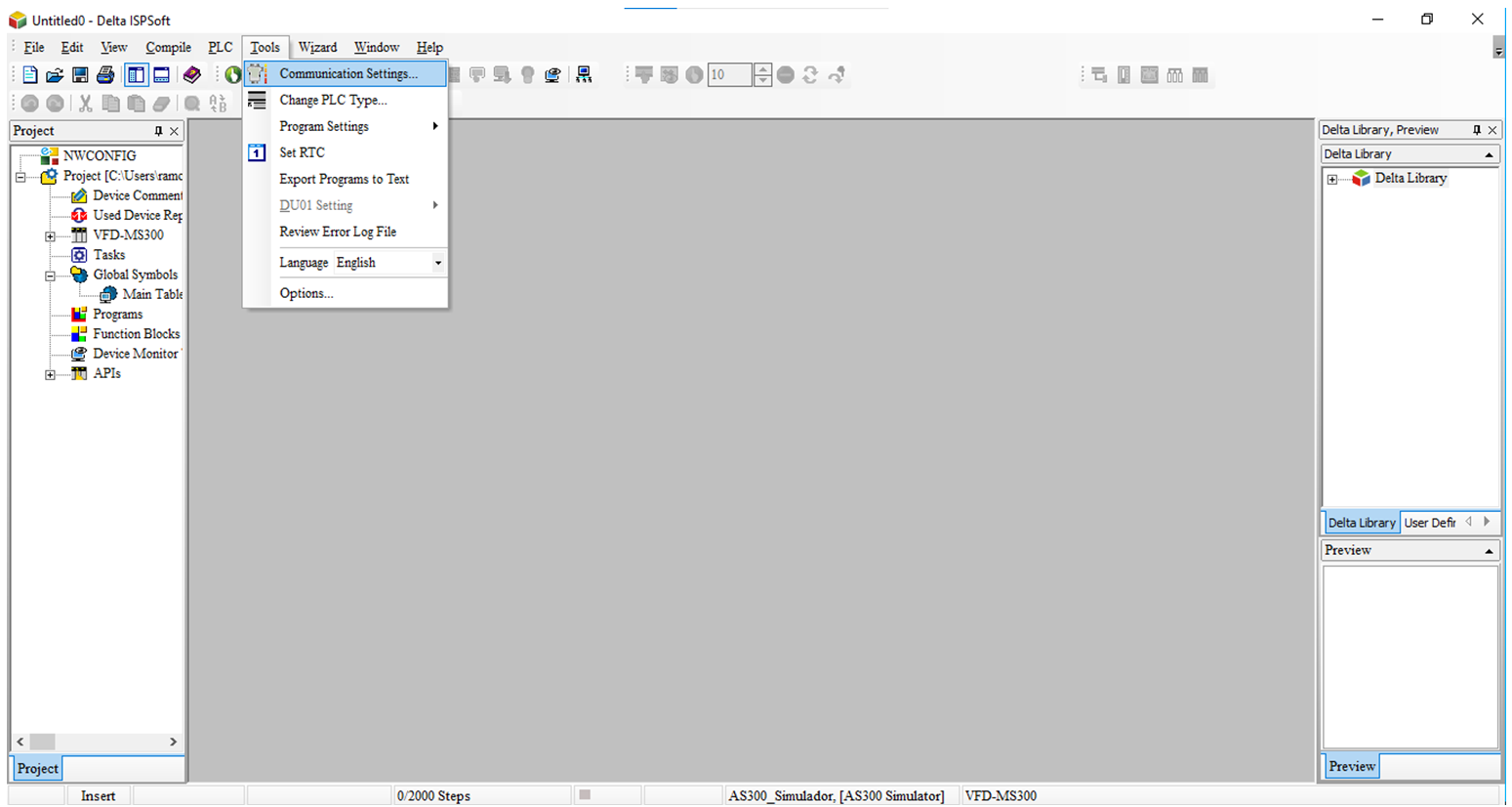
8. Na seleção de “Tools” e “Communication Settings…” selecionar a comunicação que criou no COMMGR:
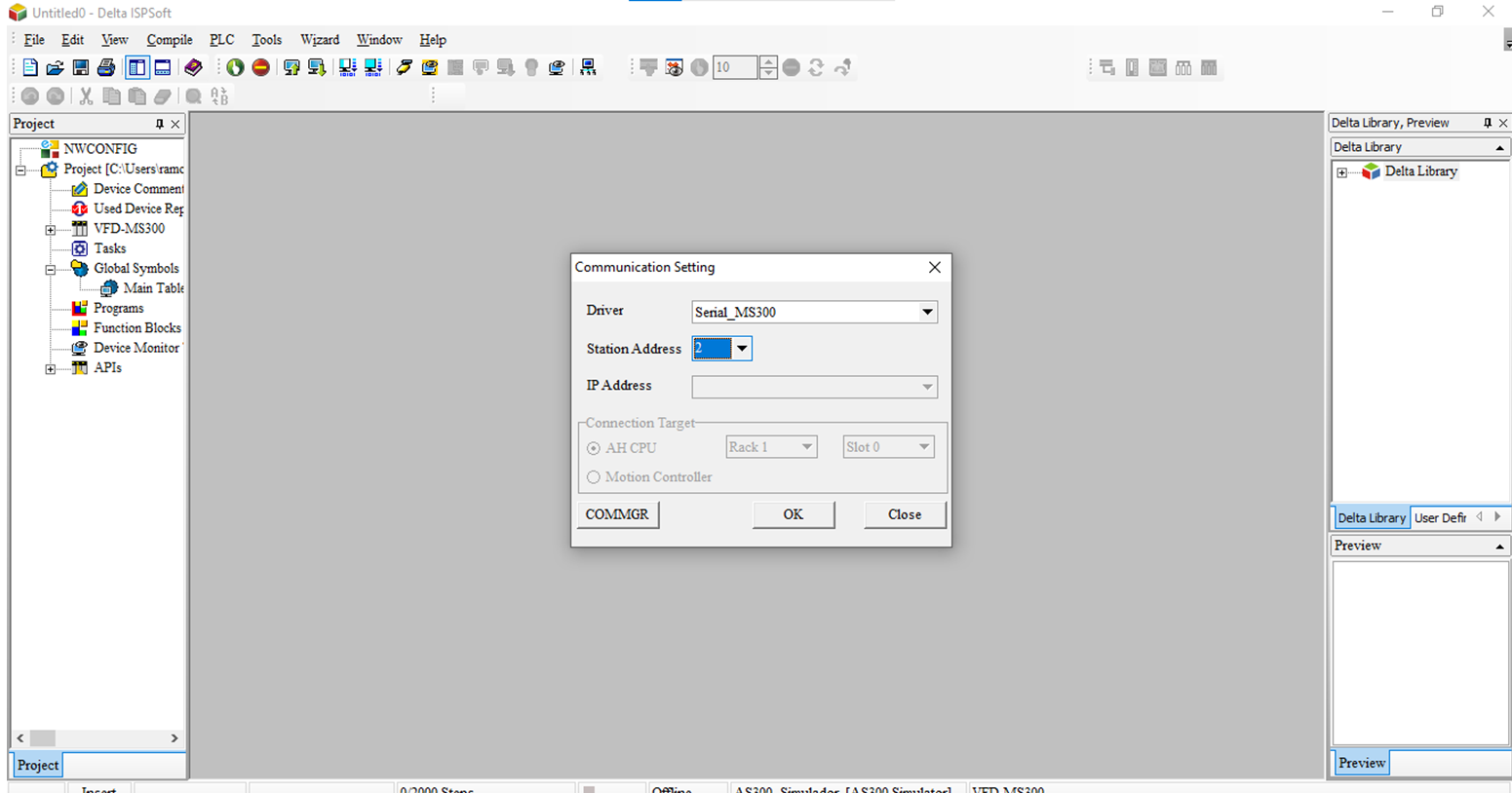
9. Selecione a comunicação e altere o ID para 2:
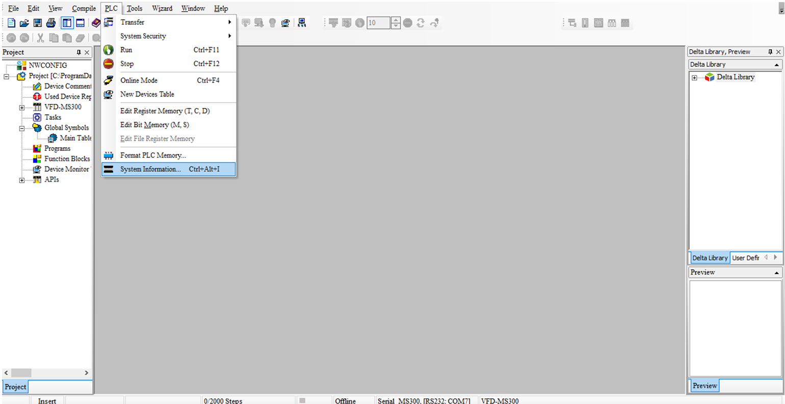
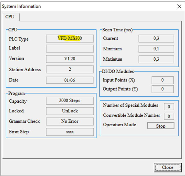
10. Na aba “CLP” na opção “System Information” ao clicar será exibida uma pop-up com informações do CLP do inversor MS300:
11. Comunicação com CLP interno MS300:
12. Crie sua lógica e descarregue no CLP interno do MS300:
13. Opção do modo online para visualizar a lógica desenvolvida:
Criando Pulso em um “Functuion Block”
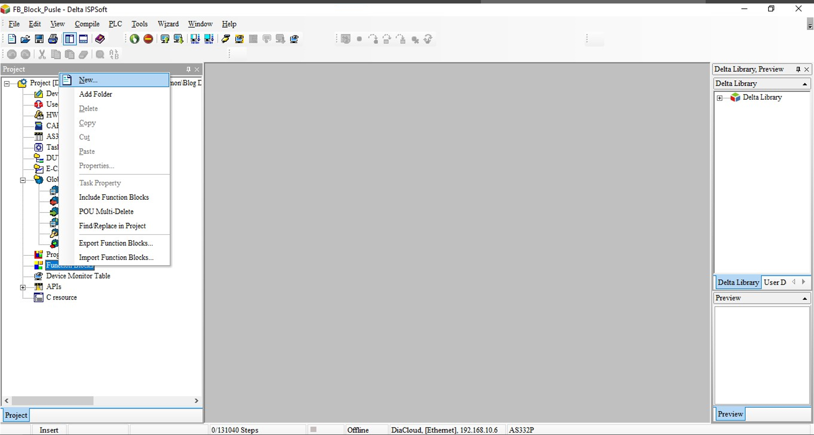
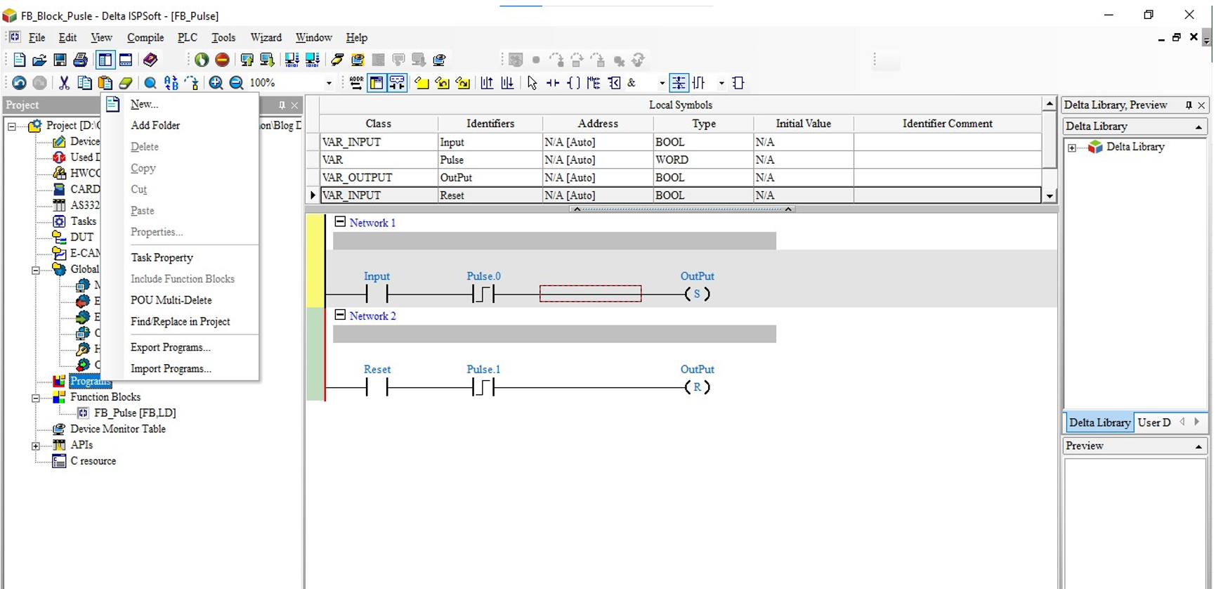
- Abra o ISPSof e selecione a opção para criar um FB (function block):
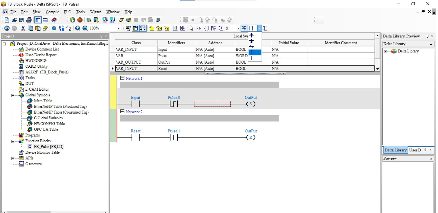
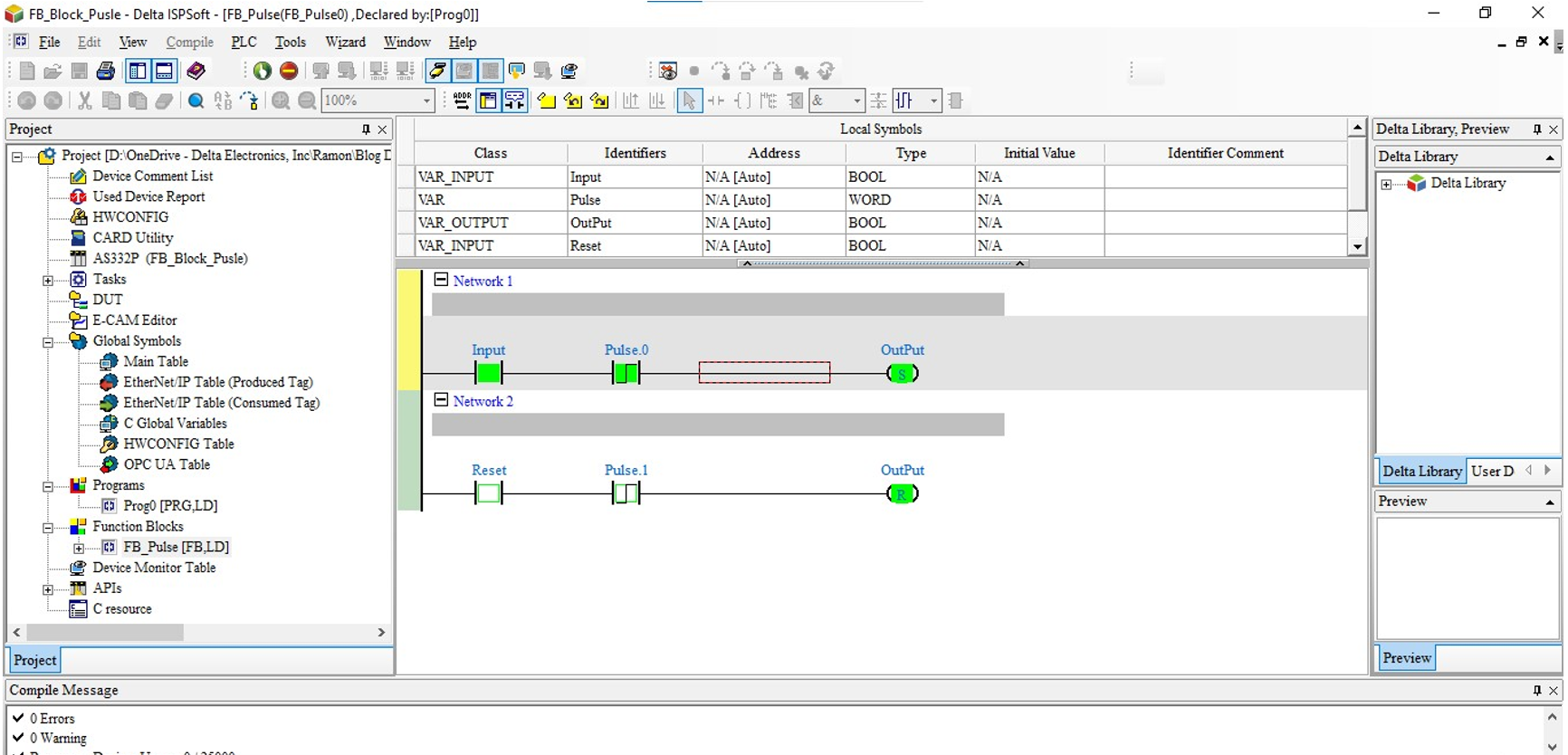
- Dentro da FB, pode criar uma lógica utilizando a função de pulso conforme demostra a imagem abaixo:
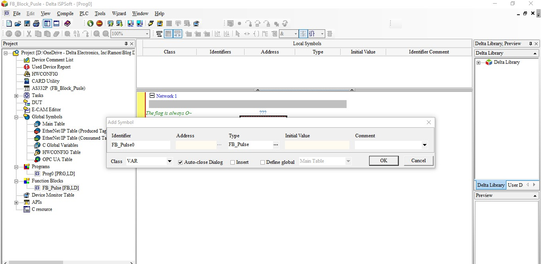
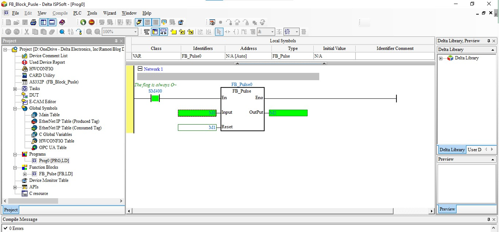
- Após criar o bloco FB, para utilizar na logica precisa criar um novo programa conforme demostra a imagem abaixo:
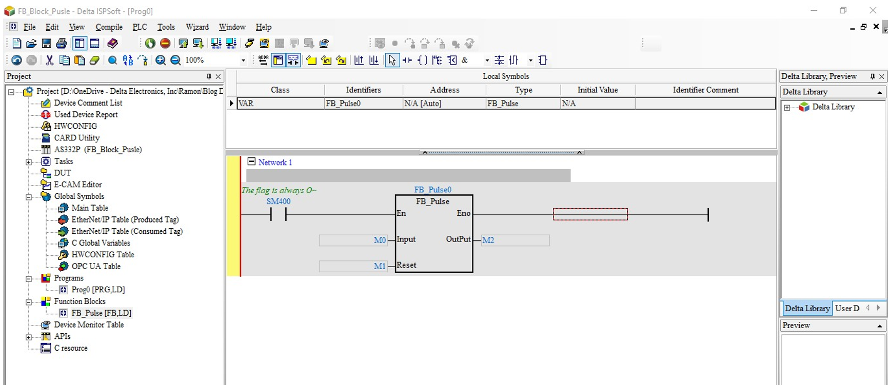
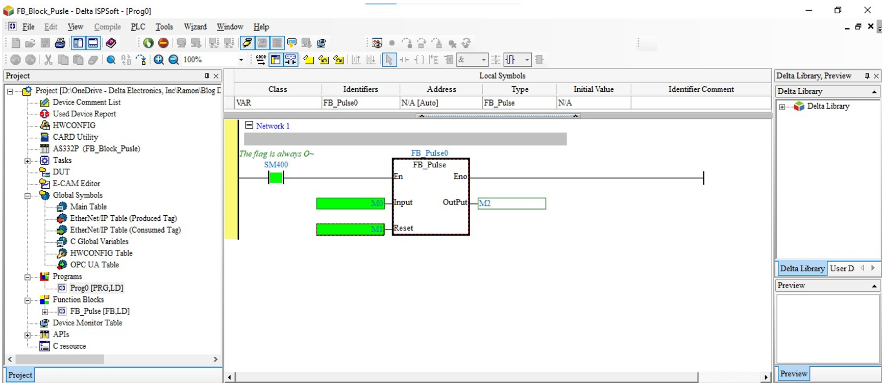
- Arreste o bloco FB para o ladder e coloque um nome:
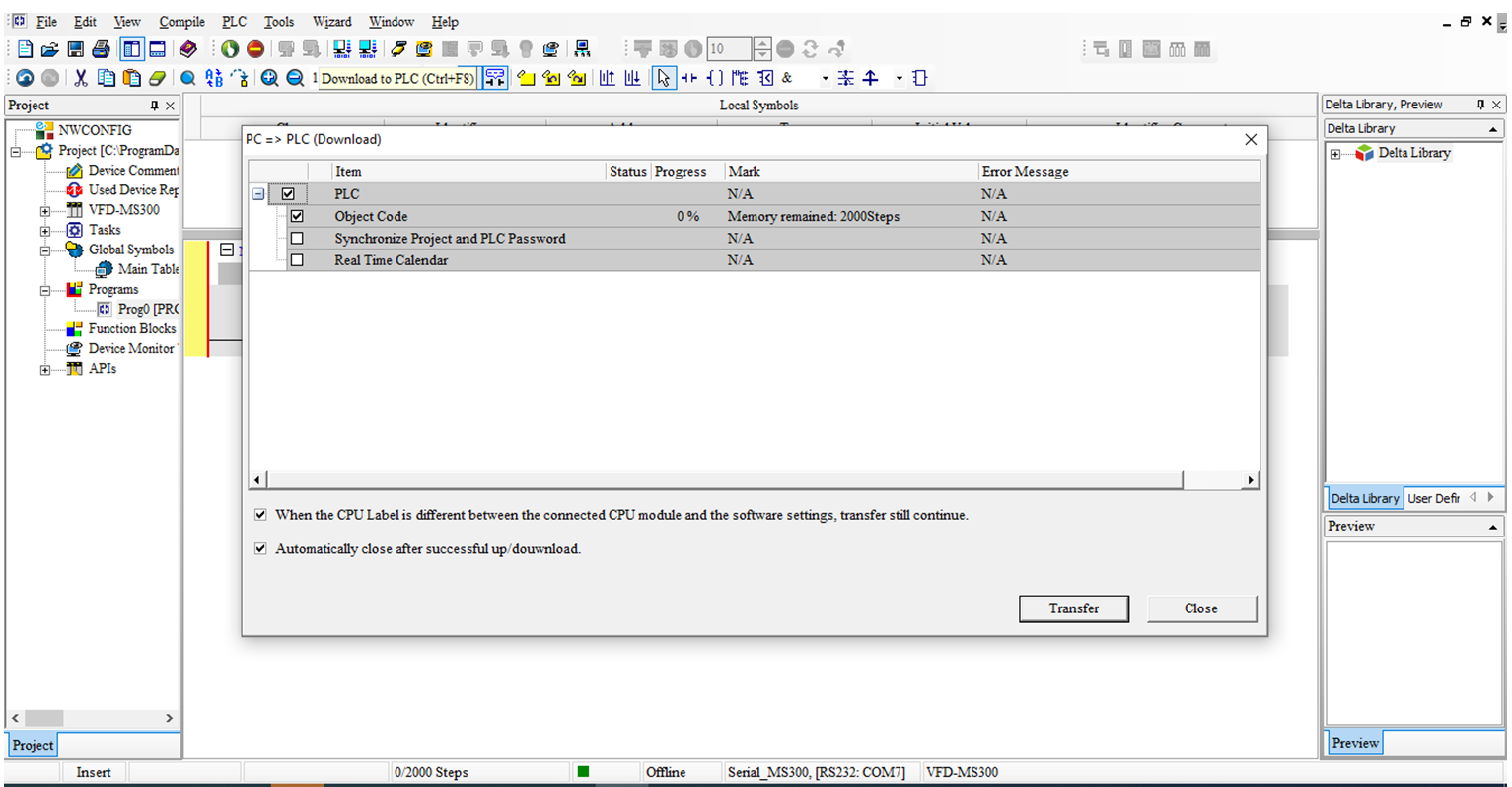
- Compile o projeto e efetue o download do programa:
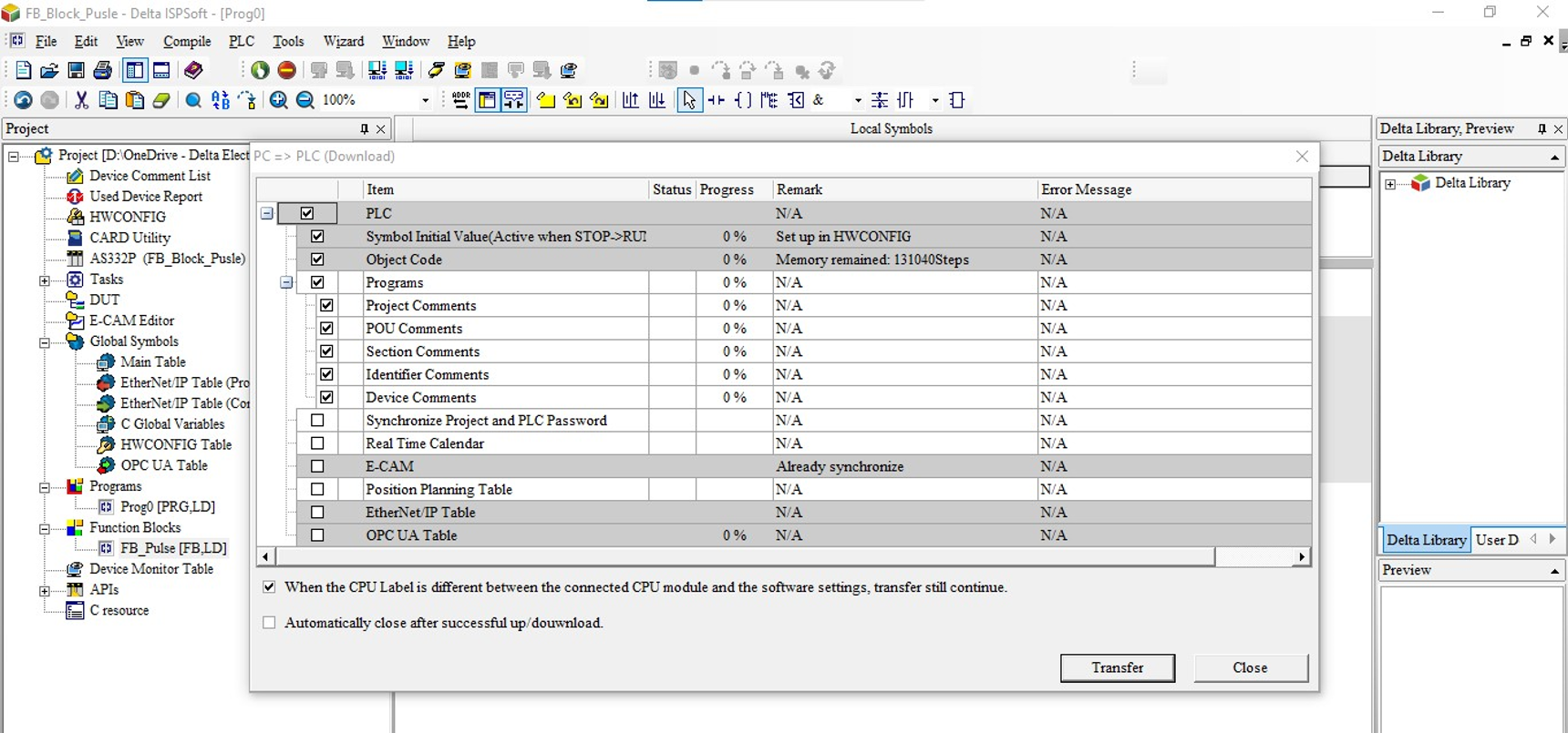
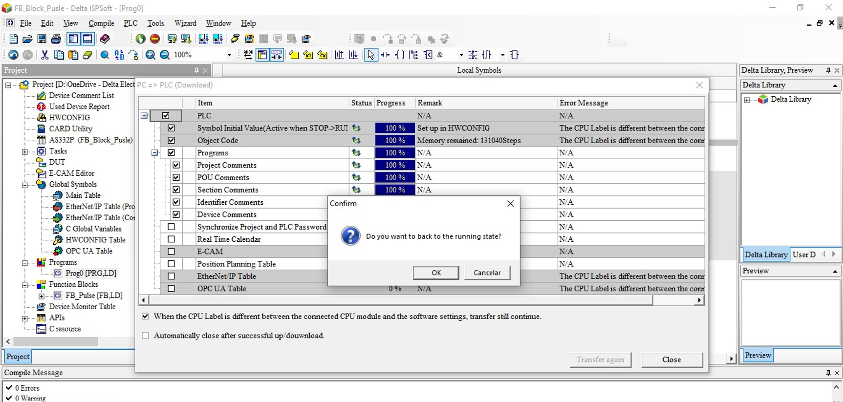
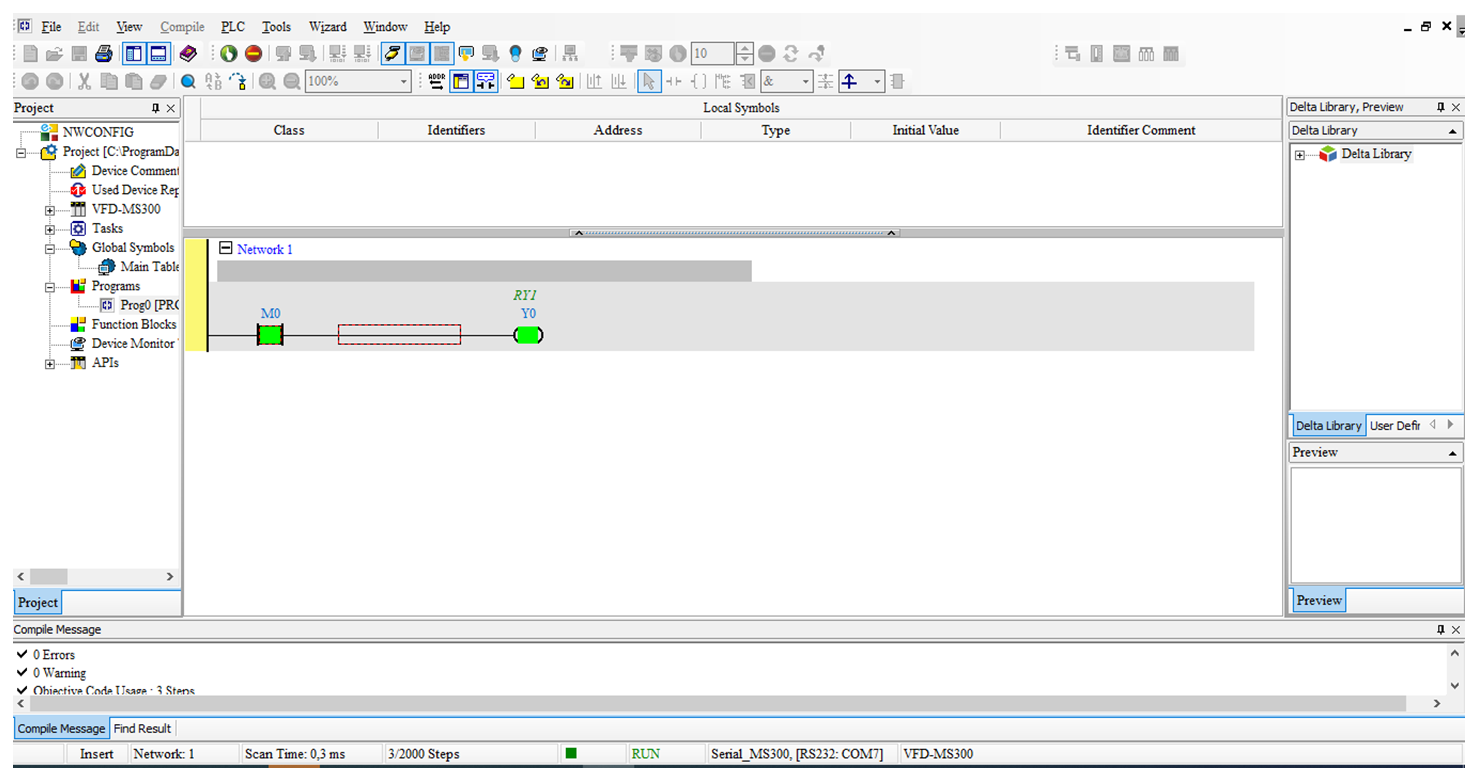
- Com o download concluído ao ficar online, pode conferir o funcionamento do bloco:
Para comunicar qualquer dispositivo modbus serial (RS485) com o CLP da TP70P, é necessário configurar a comunicação na mesma faixa e utilizar de blocos para escrita e leitura, pode utilizar dois modos para efetuar a configuração da porta serial de comunicação.
Assista o vídeo passo a passo:
Abaixo um passo a passo:
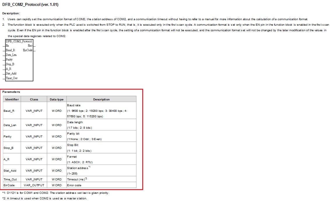
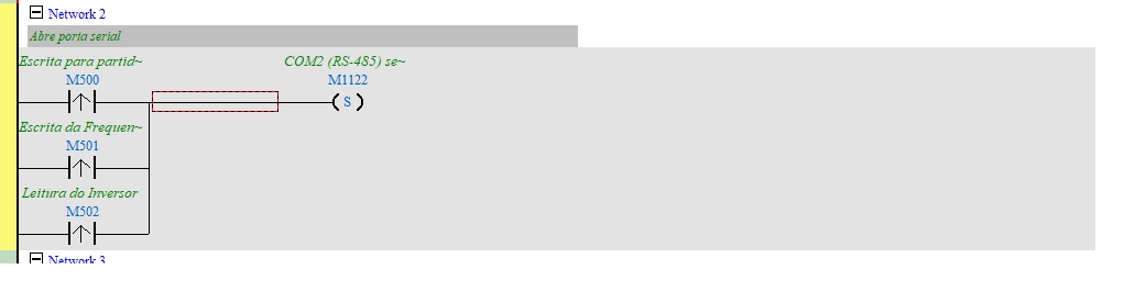
- Movendo valores para memorias especificas de configuração da porta serial, como exemplo COM2 em rede modbus 485, com os parâmetros baud rate (9600), data bits (7), paridade (even), stop bit (1), ASCII e ID do CLP como 1.
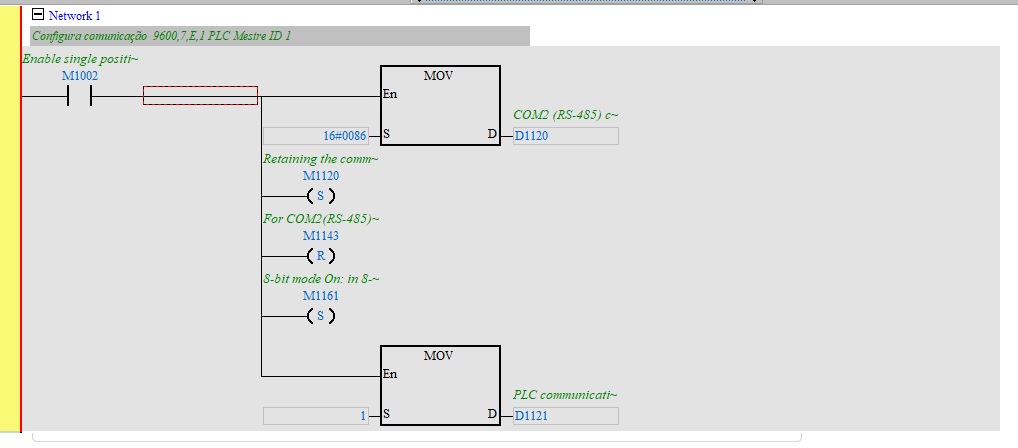
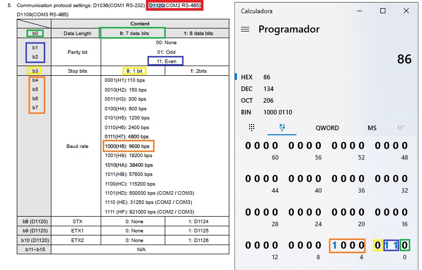
O valor do MOV na primeira linha de 16#0086 para a word D1120, está utilizando a sequência de bits demostrada na imagem abaixo, para configurar a porta COM2 em modbus RS485 como: 7, E, 1, 9600:
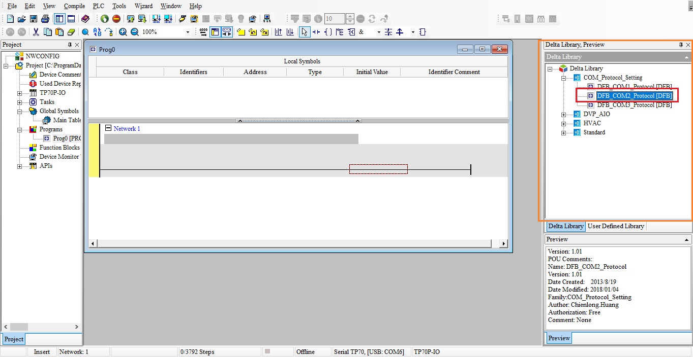
- Pode utilizar o bloco para definir a configuração da porta serial:
Selecionar a porta na biblioteca conforme demostra a imagem abaixo:
Arrastar para linha e configurar o bloco de acordo com a configuração da rede modbus, 9600/7/E/1 ASCII ID1:
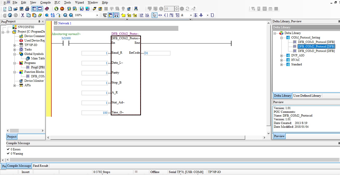
No help do bloco pode conferir os parâmetros de configuração:
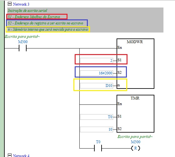
Após configurado o protocolo deve utilizar bloco de escrita (MODWR) e bloco de leitura (MODRD) para enviar e ler dados na rede modbus, no entanto cada bloco deve ser acionado de maneira individual:
Exemplo utilizando bloco de escrita (MODWR) para enviar comando na word (2000h) do inversor MS300 de partida/parada/sentido de giro:
O bloco utilizado para leitura na rede modbus neste exemplo foi MODRD, conforme demostra o exemplo abaixo de leitura do inversor MS300 com a leitura na word (2100h):
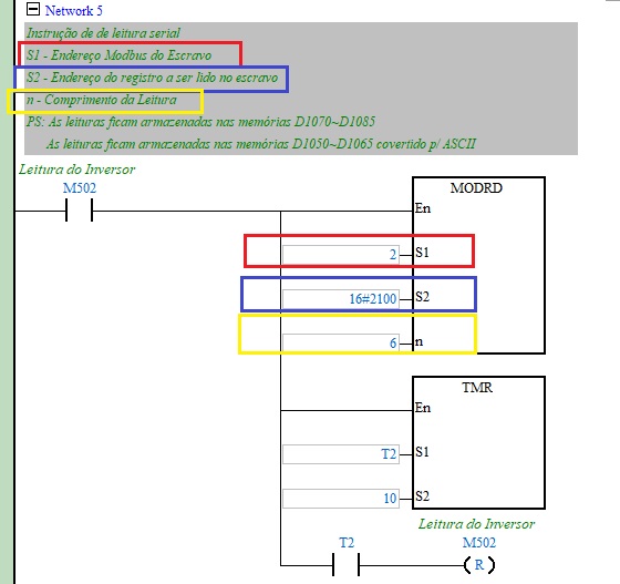
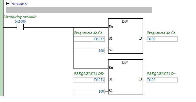
Ao efetuar a leitura utilizando o bloco MODRD os valores são armazenados nas word (D1050~D1055 ou D1070~D1085):
Após efetuar a leitura ou escrita é necessário acionar a memória M1122 para disparo da porta serial:
Para auxilio segue o link para baixar o exemplo do FAQ.
Clique aqui para baixar o exemplo -> Programa CLP MODRDeMODWR_TP70
Nesse FAQ mostraremos como a IHM altera a hora do sistema do CLP (RTC – Real Time Clock)
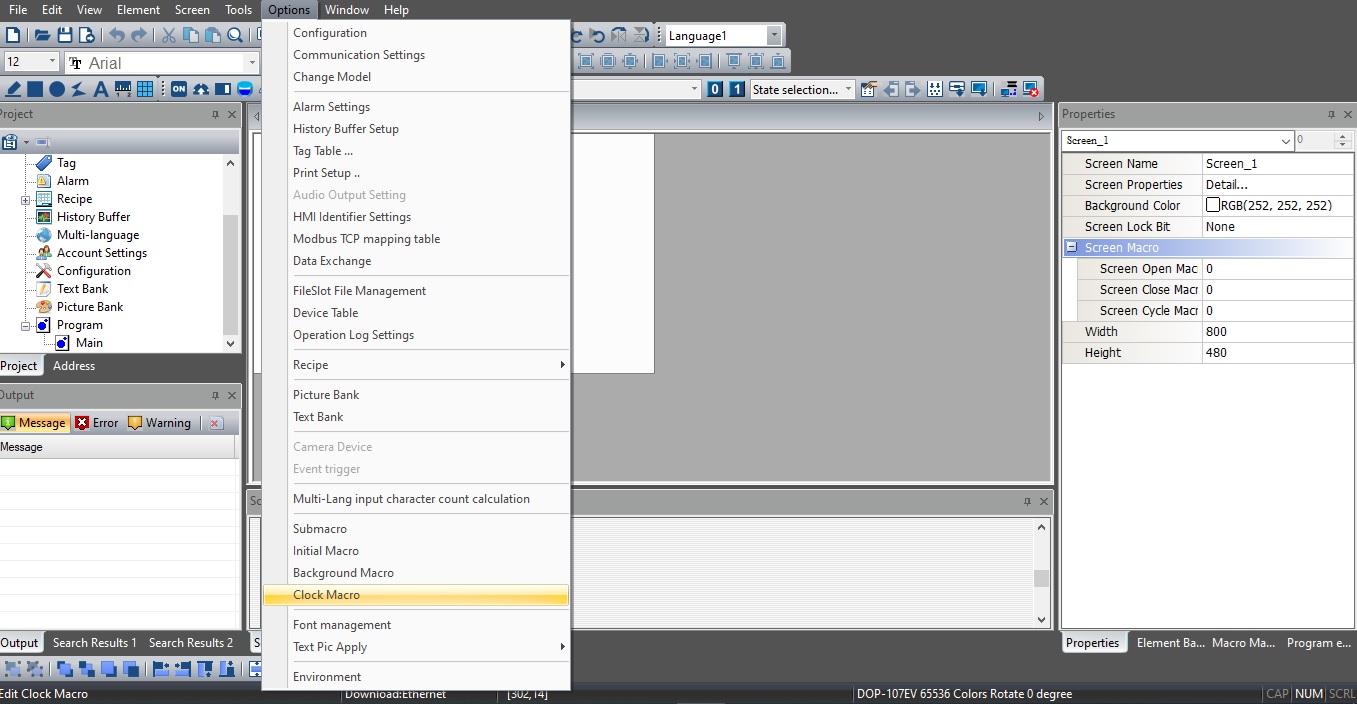
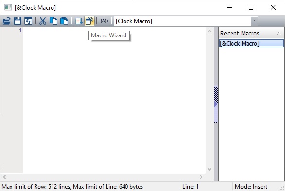
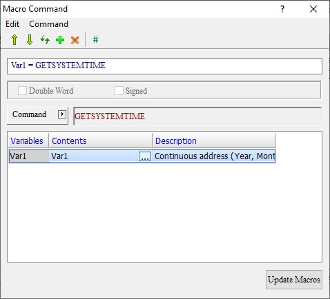
- Abrir uma Clock Macro:
- Utilizar o Wizard:
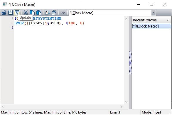
- Selecionar o “GETSYSTEMTIME” para escrever a hora e data da IHM para um memória interna:
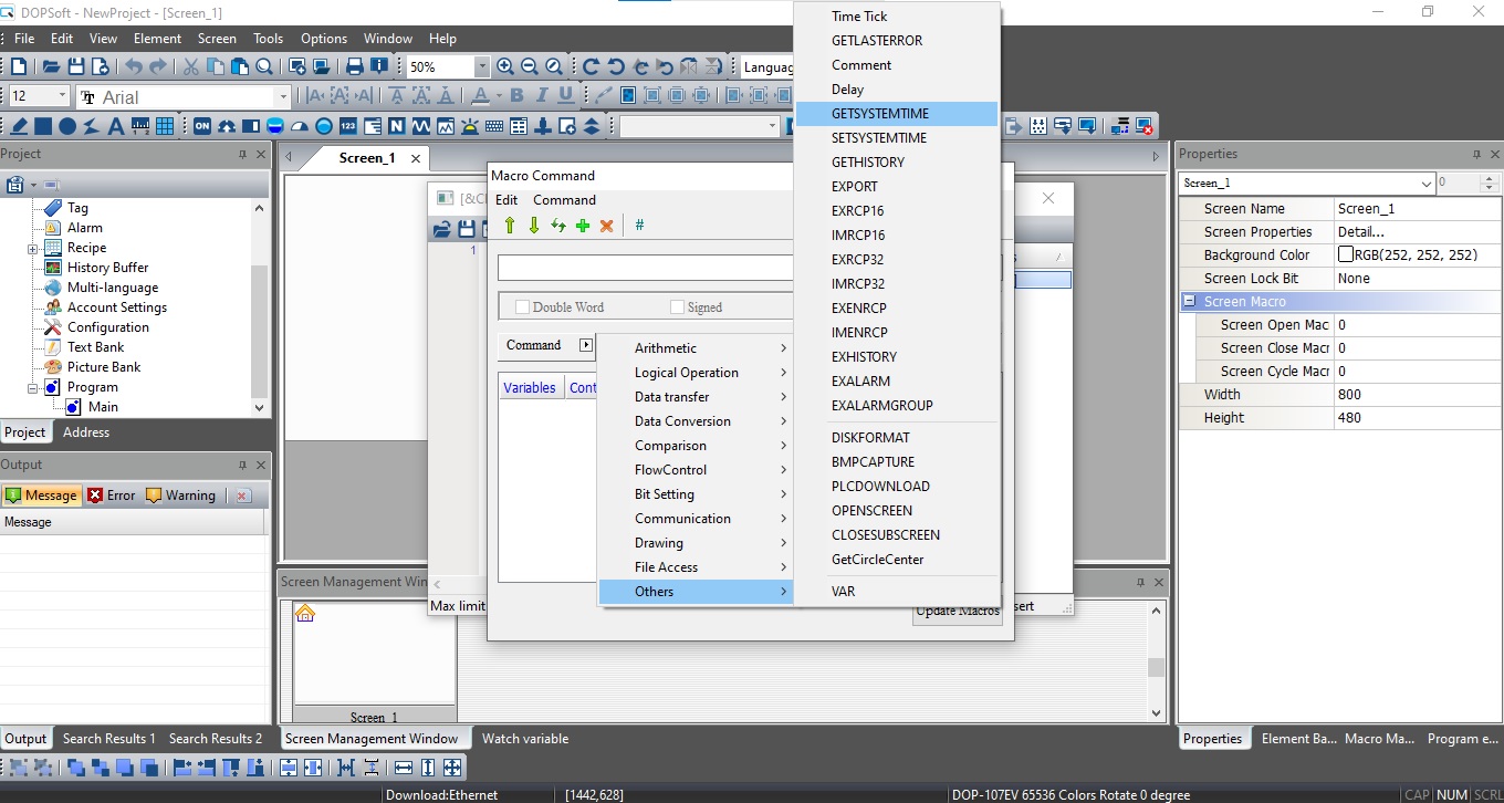
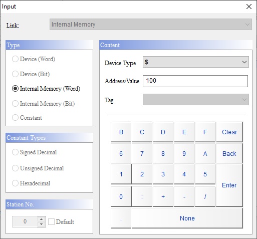
- Selecionar a memória interna:
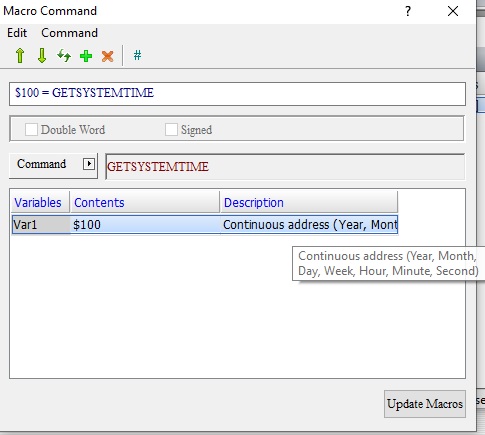
- Macro criada será enviado os dados de (Ano, Mês, Dia, Dia da Semana, Hora, Minuto e segundo) para as variáveis (D100, D101, D102, D103, D104, D105 e D106)
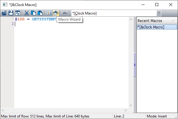
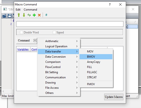
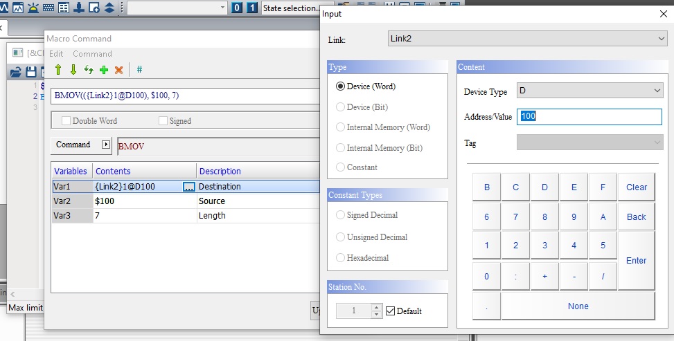
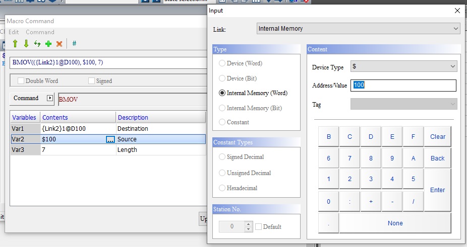
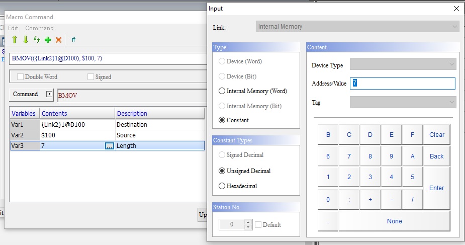
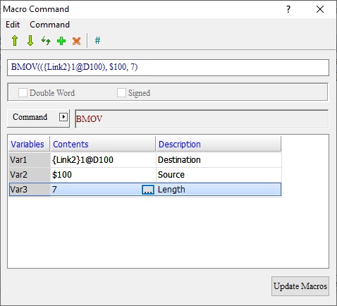
- Criar outra macro para mover os valores da D100~106 para uma variável do CLP, pode utilizar o bloco BMOV para enviar sequencial ou criar o bloco MOV para mover cada informação de forma individual:
- Com as macros criadas basta clicar no botão de “Upload” após
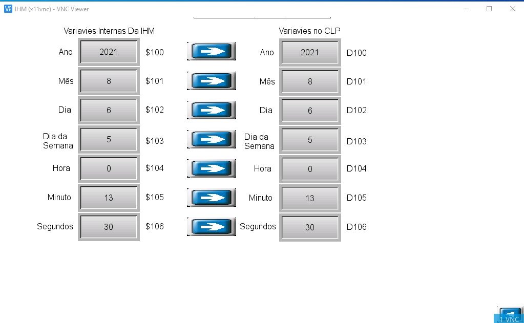
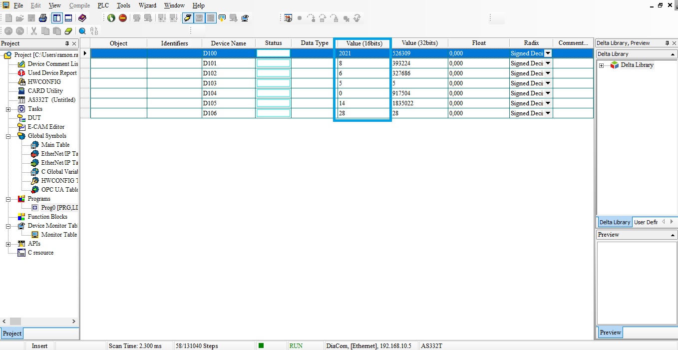
- Visualização da hora e data online com a IHM e com CLP:
ISPSoft online com o CLP:
para mais detalhes baixe o exemplo:
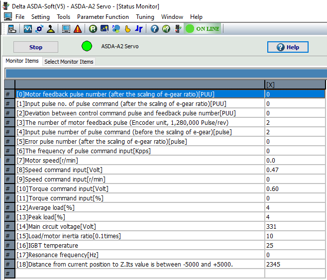
Na entrada analógica do servo drive é comum a presença de pequenos ruídos de tensão (mV). Na imagem abaixo nota-se que, mesmo sem ligação elétrica na entrada analógica, existe um pequeno sinal de tensão (mV) no comando de velocidade e torque.
Para eliminar esse ruído, siga os passos a abaixo:
Comando de velocidade (Speed Command Input):
1. Retire todas as ligações elétricas da entrada analógica e deixe o servo desabilitado (Servo Off).
2. Ajuste o parâmetro P2-08 = 20 para habilitar a escrita no parâmetro P4-10.
3. Ajuste o parâmetro P4-10 = 1 (Execute analog speed input drift adjustment).
Comando de torque (Troque Command Input):
1. Retire todas as ligações elétricas da entrada analógica e deixe o servo desabilitado (Servo Off).
2. Ajuste o parâmetro P2-08 = 20 para habilitar a escrita no parâmetro P4-10.
3. Ajuste o parâmetro P4-10 = 2 (Execute analog torque input drift adjustment).
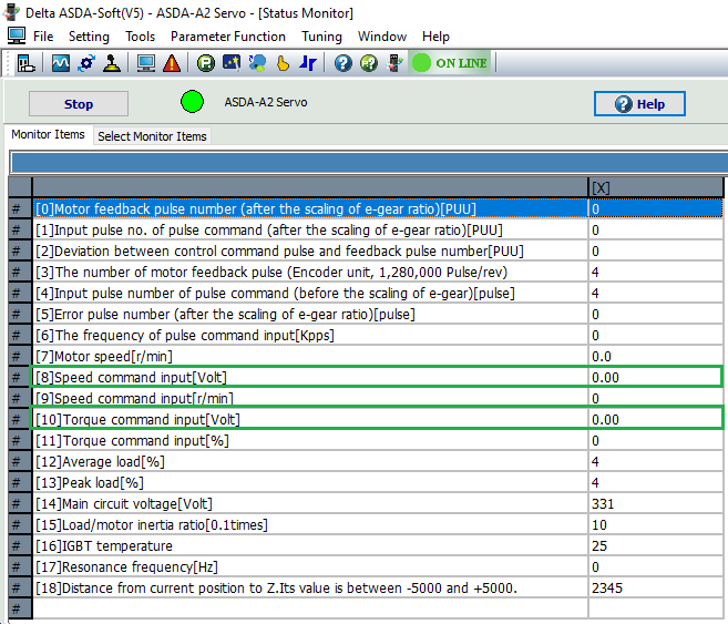
Após os ajustes, o ruído será eliminado.
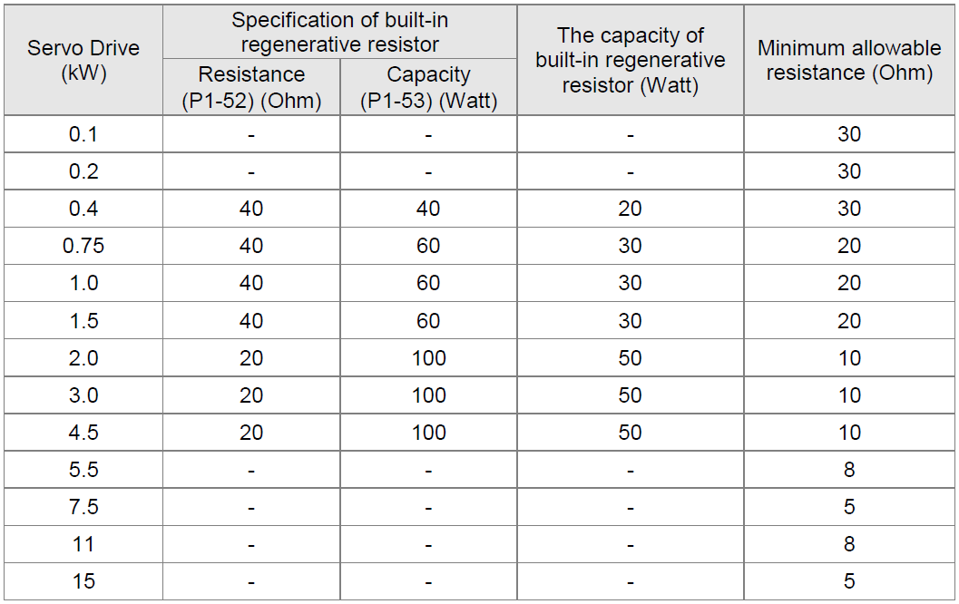
Quando uma falha, ALE05 (Erro de Regeneração) é detectada na unidade servo, indica que a energia regenerativa retornou da carga para o servo drive e excede a capacidade de processamento. Esta energia será transmitida para a capacitância do barramento CC e resultará no aumento da tensão. Quando a tensão sobe muito, o sistema servo precisa dissipar a energia extra usando um resistor regenerativo. O servo drive da série ASDA-A2 fornece um resistor regenerativo embutido como padrão de fábrica. Os usuários também podem conectar um resistor regenerativo externo se for necessária mais capacidade regenerativa. A tabela a seguir mostra as especificações do resistor regenerativo embutido do servo drive e a quantidade de poder regenerativo (valor médio) que ele pode processar.
Série ASDA-A2 220V
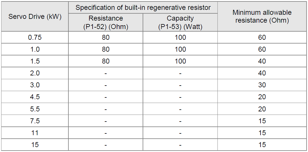
Série ASDA-A2 400V
Por favor, preste muita atenção às seguintes notas ao usar um resistor regenerativo.
- Certifique-se de que os valores de resistência (P1-52) e potência (P1-53) estejam corretamente definidos.
- Ao instalar um resistor regenerativo externo, certifique-se de que seu valor de resistência seja o mesmo que a resistência do resistor regenerativo embutido. Se combinar vários resistores regenerativos de pequena capacidade paralelamente para aumentar a capacidade do resistor regenerativo, certifique-se de que o valor de resistência do resistor regenerativo está em conformidade com as especificações listadas na tabela acima.
- Em geral, quando a quantidade de energia regenerativa (valor médio) que pode ser processada está abaixo da razão de carga nominal, a temperatura de resistência aumentará para 120°C ou mais (quando a regeneração ocorre continuamente). Por razões de segurança, a ventilação forçada é uma boa maneira de reduzir a temperatura dos resistores regenerativos. Também recomendamos o uso de resistores regenerativos com interruptores térmicos. Quanto às características de carga dos resistores regenerativos, consulte o fabricante.
- Ao usar um resistor regenerativo externo, conecte-o a P e C e certifique-se de que o circuito entre P e D esteja aberto. Recomendamos o uso de resistores regenerativos externos com valores de resistência que seguem a tabela acima (Especificações de Resistores Regenerativos Embutidos).
Referência: Manual do usuário – ASDA-A2, página 50 (2.8 Selection of Regenerative Resistor).
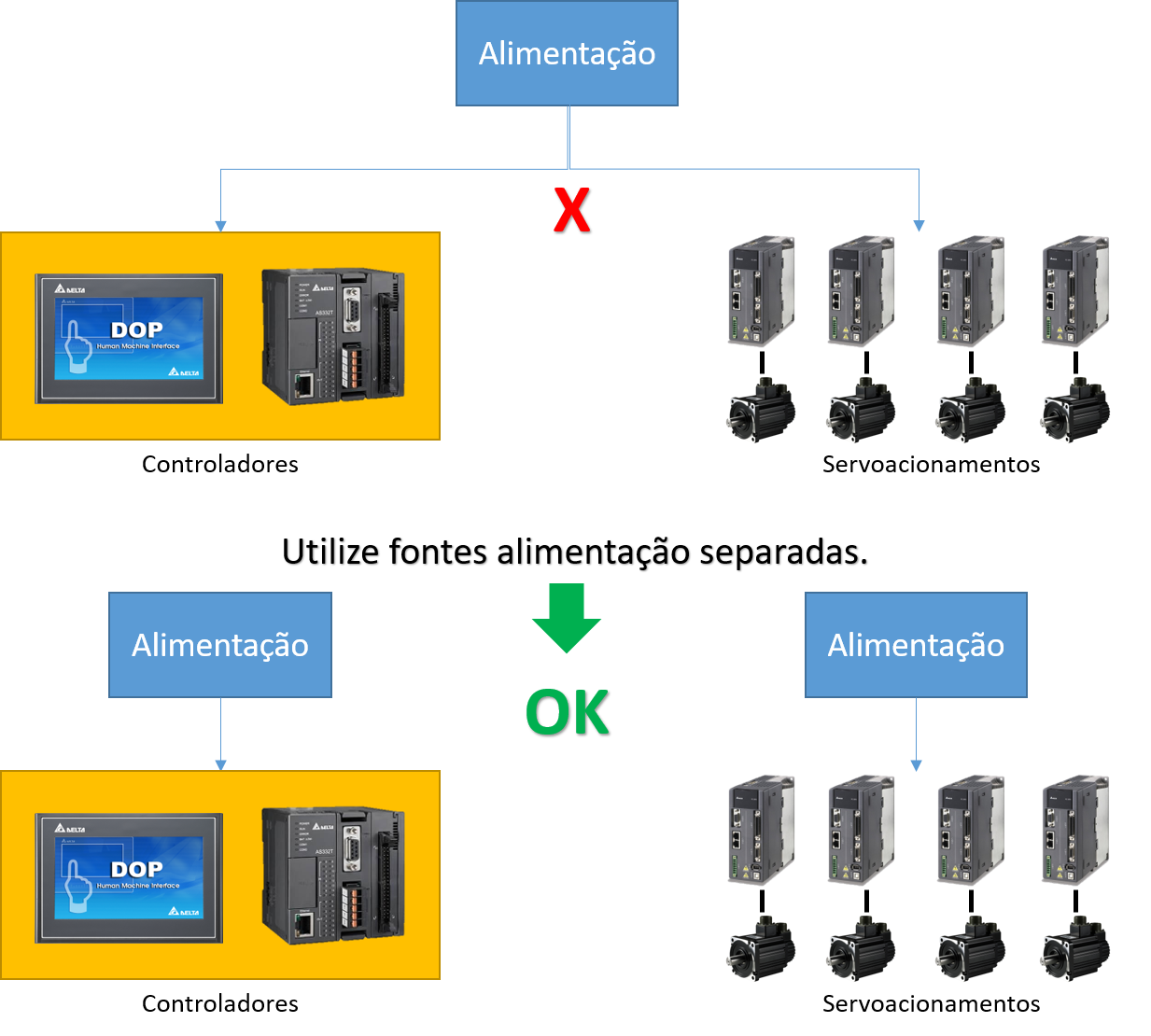
Quando um servoacionamento CA é comutado para “Servo On”, ele gera ruídos de alta ou baixa frequência durante a operação e pode interferir com equipamentos periféricos (Ex.: CLP, IHM e etc.) através de condução ou radiação, o que muitas vezes resulta em erros de comunicação ou operações anormais. Os seguintes métodos podem resolver esse problema:
- Potência separada do servoacionamento e controlador uma vez que o (EMI) gerado pelo servo geralmente influência nos controladores, como Interfaces Homem Máquina (IHM) e Controladores Lógicos Programáveis (CLP) através do circuito de energia, recomenda-se, portanto, a separação da energia do servoacionamento e dos controladores para reduzir o efeito (EMI).
- Blindagem de cabo para minimizar interferência eletromagnética. Recomenda-se utilizar cabo de par trançado blindado para comunicações. Isso ajudará a reduzir o ruído (EMI) nos controladores por radiação ou condução.
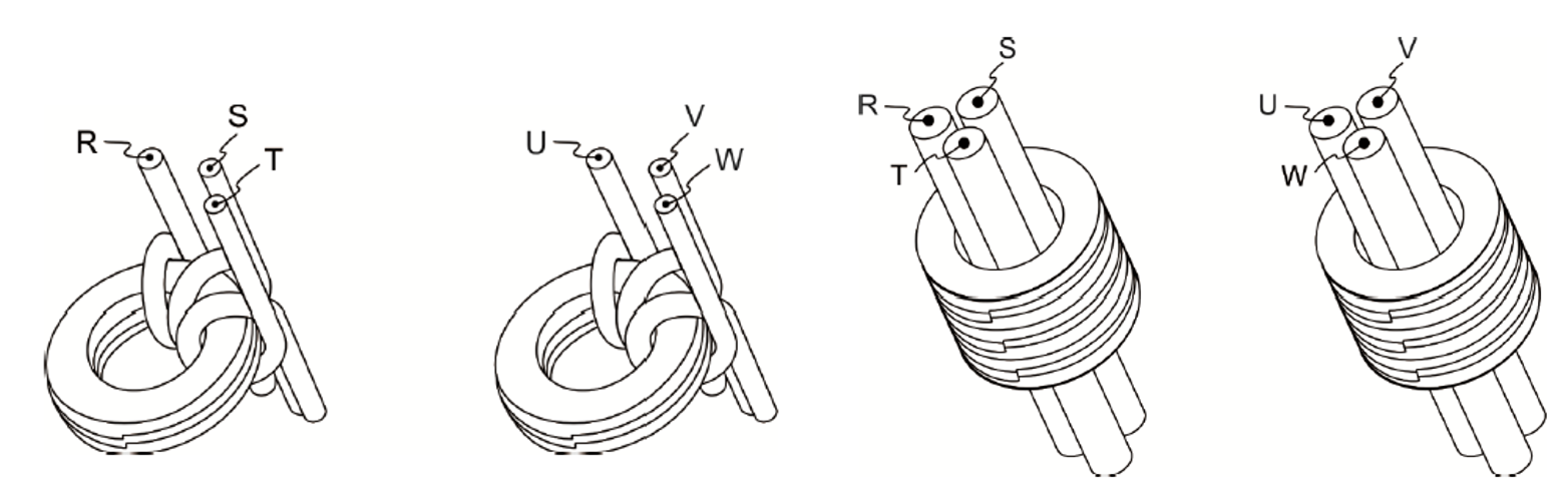
- Enrole o ferrite nos terminais de conector de energia RST e UVW do servoacionamento CA. Quando o sistema de servo CA é comutado para “Servo On”, a interferência (EMI), como sinais comuns de alta frequência, aparecem. O uso de anéis ímãs de ferrite reduz efetivamente a interferência de sinal de alta frequência em cabos de alimentação, cabos de sinal e conectores, para que sinais normais possam ser transmitidos.
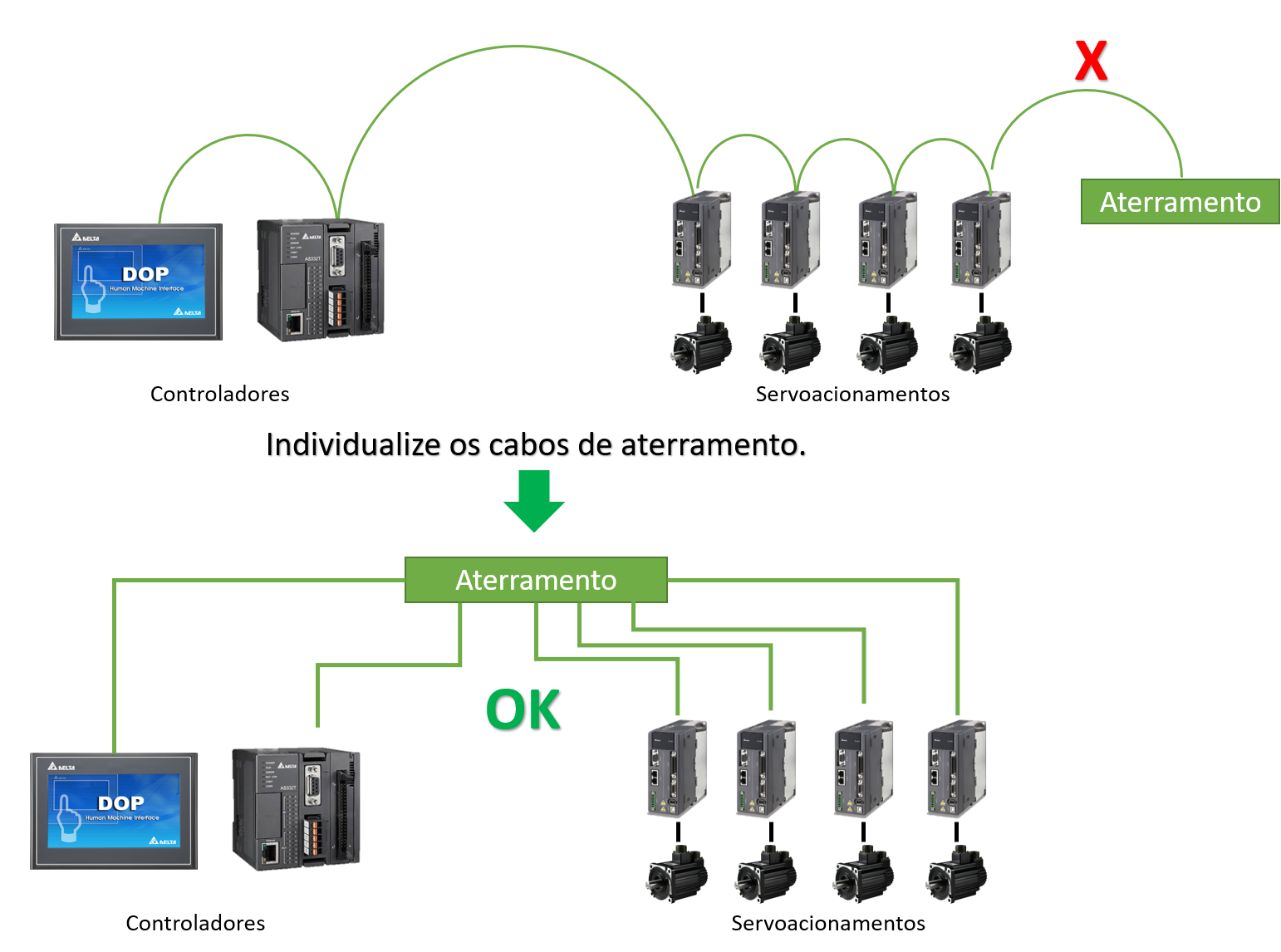
- Dispositivos devidamente conectados ao aterramento (por exemplo, placas de servo drives AC) frequentemente experimentam fugas elétricas que interferem com equipamentos periféricos através de objetos metálicos, como fios e parafusos. A melhor maneira de evitar esse problema é usar um cabo de terra para cada servo drive CA e um para cada controlador para se conectar ao terminal terra. A razão é que se os motores dos servo CA e os controladores estiverem conectados por um único cabo de terra ao terminal de aterramento, a fuga elétrica afetará imediatamente outros equipamentos periféricos através do cabo e criará uma interferência maior; em segundo lugar, a área do último contato no fio terra é muito pequena para impedir efetivamente que as fugas elétricas interfiram nos outros dispositivos.
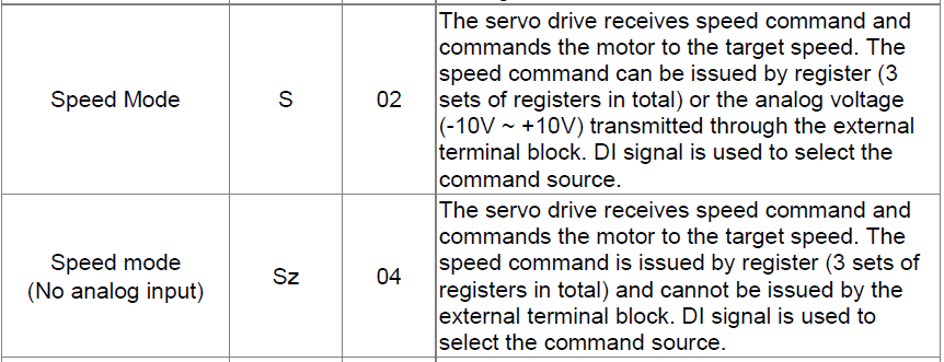
Há duas fontes de comandos de velocidade: uma é a entrada externa de tensão analógica, e a outra são os parâmetros internos. Os registros do Servo Drive da Delta permitem que os usuários configurem 3 tipos diferentes de comandos de velocidade, que são os parâmetros internos de P1-09, P1-10 e P1-11 (Unidade: 0.1rpm). Ele pode ser comutado pelos sinais SPD0 e SPD1 no conector CN1, explicados na tabela a seguir:
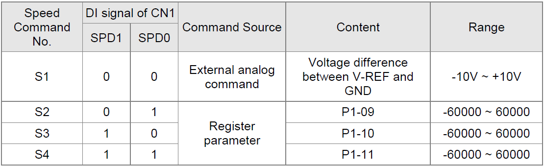
Status do SPD0 e SPD1: “0” é circuito aberto, “1” é circuito fechado. Quando SPD0=SPD1=0, e se o modo de controle é o “Sz”, então o comando é 0. Assim, se os usuários não precisarem usar a tensão analógica como comandos de velocidade, eles podem optar pelo modo “Sz” para evitar uma mudança causada pelo ruído na tensão analógica.
Se o modo for “S”, então o comando é via referência analógica (REF). A tensão de entrada analógica e a diferença de tensão entre GND tem o intervalo -10V a +10V. A velocidade correspondente à tensão é ajustável em P1 – P40.
Referência: Manual do usuário – ASDA-A2, páginas 196 e 220.
O sinal de freio (BRKR) controla relé auxiliar para fornecer potência ao freio. Veja a operação abaixo para definir as funções e a fiação da saída digital (DO).
- Configuração da saída digital (DO): Defina o valor do parâmetro da DO para 0x08 (BRKR). Pode-se ajustar os atrasos de liberação e acionamento do freio nos parâmetros P1-42 e P1-43.
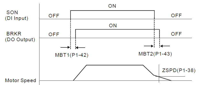
- Consulte o diagrama de interligações elétricas abaixo para usar o freio eletromagnético.
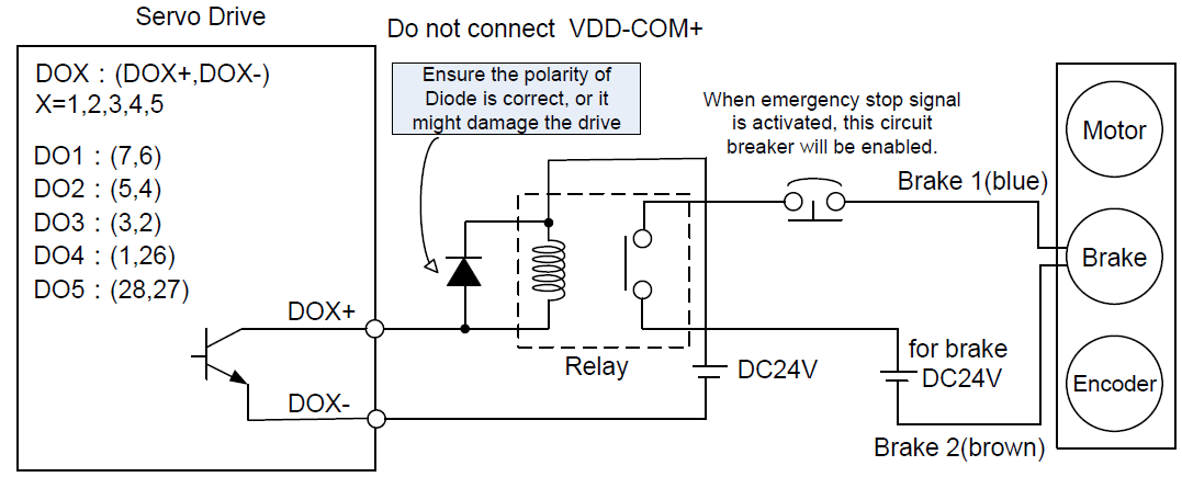
Notas:
- A bobina do freio não tem polaridade.
- Não utilize a potência do freio e a potência de controle (VDD) ao mesmo tempo.
Referência: Manual do usuário – ASDA-A2, página 257 (6.6.4 The Use of Brake).
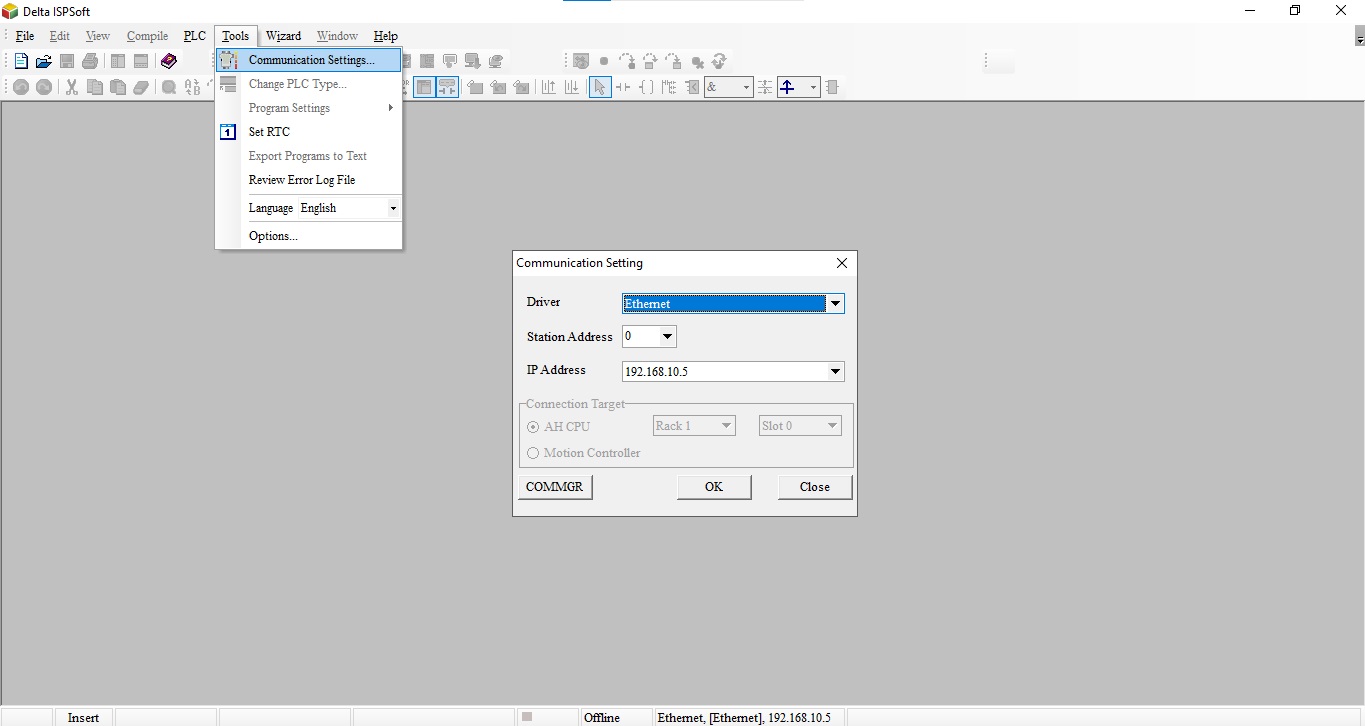
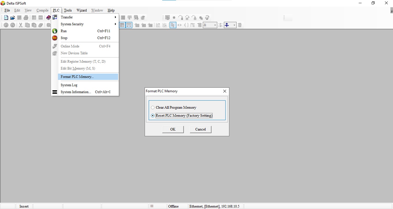
Abra o ISPSoft (passo 1) -> “Communication Settings” Selecione a comunicação com o CLP (passo 2) -> PLC “Format PLC Memory” pressione Ok (passo 3) -> o CLP voltará para a configuração de fábrica, tire a alimentação e retorne wwwà alimentação ao CLP. A senha e o programa seriam todos apagados.
- Abra ISPSoft:
- Comunicação e Seleção da comunicação:
- PLC formatar aos padrões de fabrica
O formato de comunicação do controlador lógico programável série DVP pode ser alterado por meio de registros especiais. Em determinadas aplicações o usuário pode esquecer o formato de comunicação, alterado e descarregando o programa ao CLP, resultando na desconexão entre um computador e a série DVP. Quando isso acontece, o usuário pode restaurar a conexão executando as seguintes etapas:
- Corte a energia do controlador lógico programável série DVP altere a chave RUN / STOP para STOP conforme mostrado na imagem abaixo.
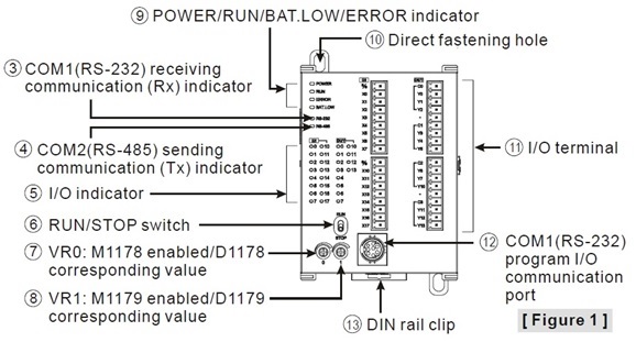
- Reinicie o controlador lógico programável DVP. Neste momento, o formato de comunicação da série DVP mudará para o valor predefinido: 9600, 7, Even, Stop bit = 1, station number = 1. O usuário pode então modificar o formato de comunicação através do software WPLSoft.
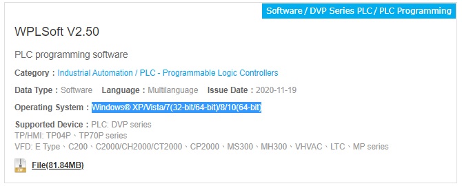
Atualmente, WPLSoft e ISPSoft só podem ser operados no sistema operacional Windows, e nenhum dos softwares são compatíveis com o sistema operacional Linux. A única maneira de usar WPLSoft, ISPSoft ou algum outro software de Automação Industrial Delta, em qualquer sistema operacional diferente do Windows (por exemplo, Mac, Linux), é utilizando maquinas virtuais para executar o sistema operacional Windows em paralelo ao sistema operacional da máquina física. Além disso, sugerimos que você instale o ISPSoft em vez do WPLSoft, pois o ISPSoft é o novo software de programação com mais funções
WPLSoft:
ISPSoft: