Introduction
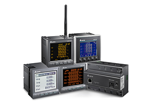
The DPM (Delta Power Meter) series precisely measures various electrical quality parameters including power factor, harmonics and current / voltage unbalance, as well as providing alarms for out-of-limit values and historical record functions. The DPM series offers a variety of communication protocols and monitoring functions that are especially suited to sectors where power quality is critical.
CAREFUL!
- Make sure the system is safe and de-energized before starting assembly, disassembly or electrical connections.
- Never short-circuit the secondary of a potential transformer (TP).
- Never open the circuit of a Current Transformer (TC).
- Use the calibration block for greater safety during maintenance or exchange (TC).
- Make sure that the secondary winding of the TC is securely attached to the equipment, as it may damage the equipment if the secondary winding comes loose during operation.
- Ground all points indicated in the connection diagram1 - Connection in NPN using internal source.
Analyzing the Features of DPM
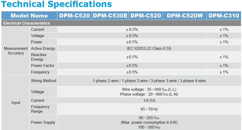
Before taking measurements, first check the electrical characteristics of the DPM such as the supply voltage and the maximum measurement voltage / current supported by the DPM. This information is found in the catalog or in the user manual for each model.
| English | Portuguese | Description |
| Wiring Method | Connection Mode | There are several connection methods for measuring voltage and current. This will depend on the form in which the power circuits to be measured are and the number of phases to be measured. |
| 1-phase 2-wire | Single-phase (2-wire) | Single-phase voltage with one phase and one neutral conductor. |
| 1-phase 3-wire | Single phase (3-wire) | Single-phase voltage with two phase conductors and one neutral. |
| 3-phase 3-wire | Three-phase (3-wire) | Three-phase voltage with three phase conductors. |
| 3-phase 4-wire | Three-phase (4-wire) | Three-phase voltage with three phase conductors and one neutral. |
| Wire Voltage (LL) | Line Voltage (FF) | Hard measured between two phase conductors. |
| Phase Voltage (LN) | Phase Voltage (FN) | Hardness measured between a phase conductor and a neutral one. |
| Current 1A / 5A | Current 1A / 5A | Maximum measuring current: 1A or 5A. This current is related to the CT secondary current (Ex .: 250 /5A) or direct measurement current (without CT). |
Connection Methods
The connection method will depend on the power installation to be measured, which and how many phases will be measured. If the system voltage to be measured exceeds the maximum measurement value, it will be necessary to use a step-down transformer known as the Potential Transformer (TP). If the current exceeds the maximum DPM measurement value, a current transformer (TC) must be used.
For line measurements (FN), consider the Y-type connection and if this measurement is not necessary, the delta type Δ connection can be considered.
See the figure below for the different connection methods
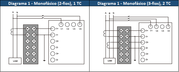
Figure 1 - Single-phase connection methods.
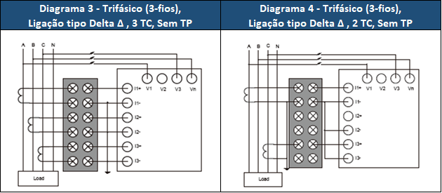
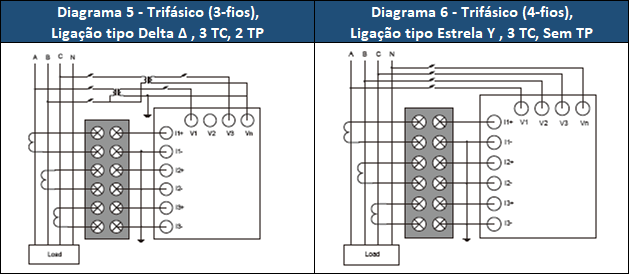
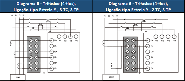
Figure 2 - Three-phase connection methods.
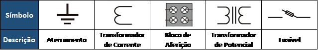
Figure 3 - Symbology.
Parameterization

Power System Adjustment
sPower System (SYS): Select the system connection method. Ex .: 3P3L means 3 phases and 3 wires. (Factory default: 3P4L).
Number of (TC): Quantity of (TC) that will be used (0 to 3). (Factory default: 3).
Number of (TP): Quantity of (TP) that will be used (0 to 3). (Factory default: 3).
Step by step to adjust the (SYS):
- Press BACK until the SETUP page appears.
- Press ► NEXT until * SYS appears, then press ▲ UP to enter the * SYS configuration page. If the menu is not showing with * SYS, press ▲ UP and ▼ DOWN for a few seconds until the options appear.
- Within the SYS configuration page, after the option is highlighted, press ▲ UP or ▼ DOWN to select the desired configuration.
- Adjust the amount of (TC) and (PT).
- When you press SET (► NEXT button) and return to the SETUP page, the setting will have been completed.
- To cancel all changes, press BACK.
* Power System (SYS) = Power System
Current Transformers (TC) Configuration
Primary winding (CT1): Current adjustment of the transformer primary with adjustment of 1 ~ 9999 A (Factory default: 1 A).
Secondary winding (CT2): Transformer secondary current adjustment between 1 A or 5 A (Factory default: 1 A).
Step by step to adjust the (TC):
- Press BACK until the SETUP page appears.
- Press ► NEXT until * CT appears, then press ▲ UP to enter the (TC) configuration page. If the menu is not showing with * CT, within the SETUP page press ▲ UP and ▼ DOWN for a few seconds until the options appear.
- Within the (TC) configuration page, when the option is highlighted, press ▲ UP or ▼ DOWN to adjust the desired value.
- Press SET (► NEXT button) to accept the value and move to the next value.
- Repeat steps (3) ~ (5) until you finish setting the values and then press SET (► NEXT button). When you press SET (► NEXT button) and return to the SETUP page, the setting will have been completed.
- To cancel all changes, press BACK.
* Current Transformer (CT) = Current Transformer (CT)
Configuration of Potential Transformers (TP)
Primary winding (PT1): Input voltage at the primary of the potential transformer with adjustable values of 1 ~ 9999 V (Factory default: 1V).
Secondary winding (PT2): Secondary output voltage of the potential transformer with adjustable values of 1 ~ 9999 V (Factory default: 1V).
Step by step to adjust the (TP):
- Press BACK until the SETUP page appears.
- Press ► NEXT until * PT appears, then press ▲ UP to enter the (TP) configuration page. If the menu with * PT is not showing, within the SETUP page press ▲ UP and ▼ DOWN for a few seconds until the options appear.
- Within the (TP) configuration page, when the option is highlighted, press ▲ UP or ▼ DOWN to adjust the desired value.
- Press SET (► NEXT button) to accept the value and move to the next value.
- Repeat steps (3) ~ (5) until you finish setting the values and then press SET (► NEXT button). When you press SET (► NEXT button) and return to the SETUP page, the setting will have been completed.
- To cancel all changes, press BACK.
* Potential Transformer (PT) = Potential Transformer (TC)
Example
Considering a three-phase system (3F + N) with phase voltage of 760Vac and maximum current of 200A, what would be the ideal connection method and the values of parameters CT1 / 2 and PT1 / 2? Consider line and phase voltage measurements.
Resolution:
For the DPM-C520, three 760 / 127Vac power transformers (TP) would be needed to lower the voltage of each phase and three 250 / 5A current transformers (TC) with a calibration block for possible maintenance.
Note: In this case, a separate circuit should be considered to supply the DPM.
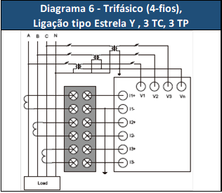
Figure 4 - Diagram chosen.
After the electrical interconnections, the DPM-C520 was parameterized with the following values:
Power System:
System (SYS): 3P4L (3 phases with 4 wires)
Number of (TC): 3
Number of (TP): 3
Current Transformers:
Primary winding (CT1): 250 A
Secondary winding (CT2): 5 A
Potential Transformers:
Primary winding (PT1): 760 Vac
Secondary winding (PT2): 127Vac
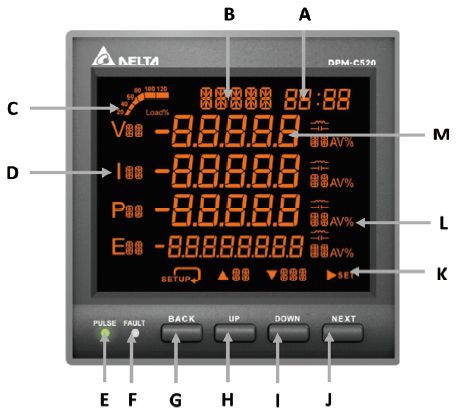
Ready! DPM will display the measured values on the display screen.