Introdução
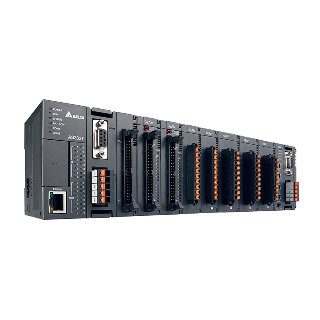
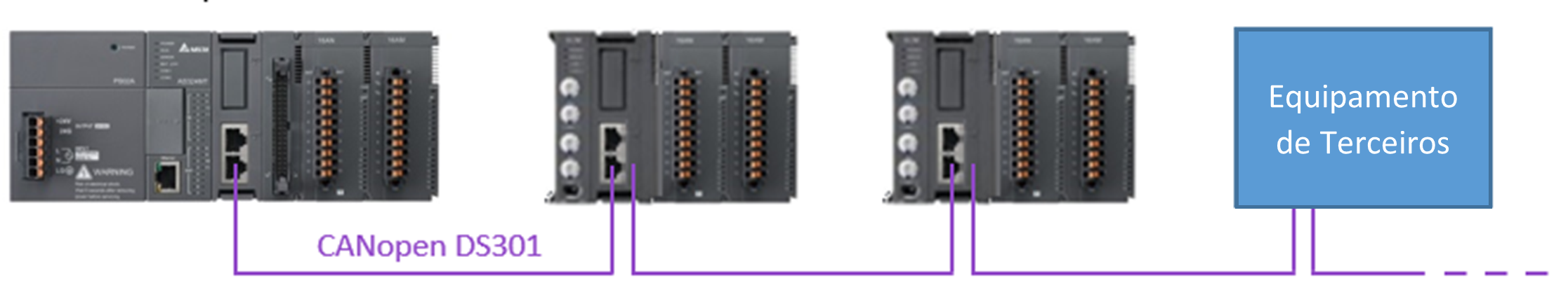
O módulo de comunicação AS00SCM-A no modo remoto (RTU) mais cartão de comunicação AS-FCOPM, possibilita a utilização junto com equipamentos de outras séries (Ex.: DVP) e com dispositivos de terceiros que trabalham com CANopen (DS301). Ao usar o CLP Delta como CPU, deve-se usar o CANopen Builder para configurar a rede e realizar os mapeamentos dos equipamentos na rede.
Obs.: Sempre será necessária uma CPU AS para configurar o SCM antes de ser utilizado.
Configuração
Quando o cartão de comunicação AS-FCOPM trabalha junto o CLP da série AS, ele suporta três tipos de modos (RTU) remote terminal unit: “AS Remote Communication”, “CANopen DS301 Mode” e “Delta Special Driver & AS Remote Mode”. Use a chave FORMAT1 para selecionar entre os três modos (RTU) remote terminal unit.
A. FORMAT 1: Chave de seleção da configuração do modo de comunicação (RTU).
B. ID1/ID2: Chave de seleção da configuração do endereço (ID de rede).
- ID1: (0 ~F) recomendado deixar igual a “0”.
- ID2: (0 ~F) endereço do escravo.
C. FORMAT2: Chave de seleção da velocidade da comunicação (RTU).
D. Modo (COM): O AS00SCM-A funcionará como um módulo de comunicação e será alimentado pelo barramento da CPU.
Modo (RTU): O AS00SCM-A funcionará como uma unidade remota e deve estar desencaixada da CPU e com alimentação independente.
Identificação e Configuração do Hardware
Antes de utilizar o módulo AS00SCM-A como uma unidade remota de I/O (RIO), deve-se fazer o download das configurações dos módulos com o auxílio de uma CPU AS. Para isso, siga os passos abaixo.
- Com o AS00SCM-A desacoplado da CPU AS, ajuste as chaves de seleção: ID1 = 0, FORMAT1 = 0 (AS Remote Communication), ID2 = 1 (endereço) e FORMAT2 = 7 (1000kbps).
- Conecte os cabos CANopen entre o AS00SCM-A e a CPU AS, encaixe os módulos de I/O, mude a chave para o modo RTU e alimente o módulo.
- Abra o ISPSoft (V3.11 ou superior) e ajuste as configurações de hardware em HWCONFIG.
- Dentro do HWCONFIG, caso seja a primeira vez que estiver configurando a CPU, faça o Scan, caso contrário faça o Upload das configurações da CPU, pois o Scan sobrescreve todas as configurações anteriores.
- Dê um duplo clique na CPU para abrir a área de edição.
- Acesse o menu Function Card 2 Setting.
- Dentro do menu, ajuste AS-FCOPM Working mode: AS Remote Communication. Este será o modo de comunicação para descarregarmos as configurações dos módulos.
- Ajuste AS Remote module No. com a quantidade AS00SCM-A que estarão trabalhando em modo RTU na mesma rede CANopen. No caso do exemplo será 1.
- Ajuste a velocidade de comunicação em AS-FCOPM Bit Rate de acordo com o comprimento da rede CANopen. Esse valor deve ser o mesmo configurado no AS00SCM-A. Consulte a tabela FORMAT2 para maiores detalhes. No caso do exemplo, será configurado como 1000kbps.
- Após isso, o AS00SCM-A aparecerá conectado na CPU no HWCONFIG. Adicione os módulos que estarão acoplados utilizando a lista de produtos. Caso adicione um módulo de I/O que não existe no AS00SCM-A, o mesmo apresentará erro.
- Faça o download das configurações.
- Neste momento, a CPU e o AS00SCM-A estarão se comunicando através do modo AS Remote Communication.
- Para trabalhar na rede CANopen DS301, agora ajuste as chaves de seleção: ID1 = 0, FORMAT1 = 4 (DS301), ID2 = 2 (endereço) e FORMAT2 = 7 (1000kbps). Obs.: O endereço deve ser maior que 1 pois, por padrão o endereço do cartão AS-FCOPM da CPU é 1 (AS-FCOPM node ID).
- Após ajustar as chaves de seleção, deve-se desligar e ligar o AS00SCM-A para que as configurações sejam aceitas.
- Agora dentro do HWCONFIG, ajuste AS-FCOPM Working mode: DS301 e mantenha o valor configurado em AS-FCOPM Bit Rate.
Se após os passos acima o LED de erro do AS00SCM-A estiver piscando, refaça os passos acima, pois é provável que algum módulo de I/O foi configurado errado ou não está acoplado.
Configurando o CANopen Builder
1. Dentro do HWCONFIG, clique com o botão direito do mouse no cartão AS-FCOPM da CPU para acessar o menu.
2. Abra o CANopen Builder (AS-FCOPM).
3. Dentro do CANopen Builder, fique online e faça o Scan da rede. O AS00SCM-A aparecerá com o ID2.
4. Clique com botão direito no AS00SCM-A e abra as propriedades para mapear os PDOs dos I/Os dos módulos.
5. Dentro das propriedades do AS00SCM-A, adicione os PDOs de acordo com a função desejada e mapeie os PDOs de cada módulo.
6. Depois dê um duplo clique na CPU para abrir as propriedades.
7. Dentro das propriedades transfira os nós disponíveis (Available Nodes) para a lista de nós (Node List). Todos PDOs serão direcionados para os endereços sequenciais.
8. Depois de mapeados, faça o download da nova configuração.
9. Agora já se pode ler e escrever na lógica de programação do CLP utilizando os endereços mapeados.
Esse mesmo procedimento pode ser feito para adicionar outros equipamentos na rede. No CANopen Builder também é possível importa arquivos EDS de outros fabricantes.