- +55 (12) 3932-2300
- [email protected]
Introduction
This article will present the step by step to configure the analog inputs and outputs of the functional cards (Function Cards) and expansion modules.
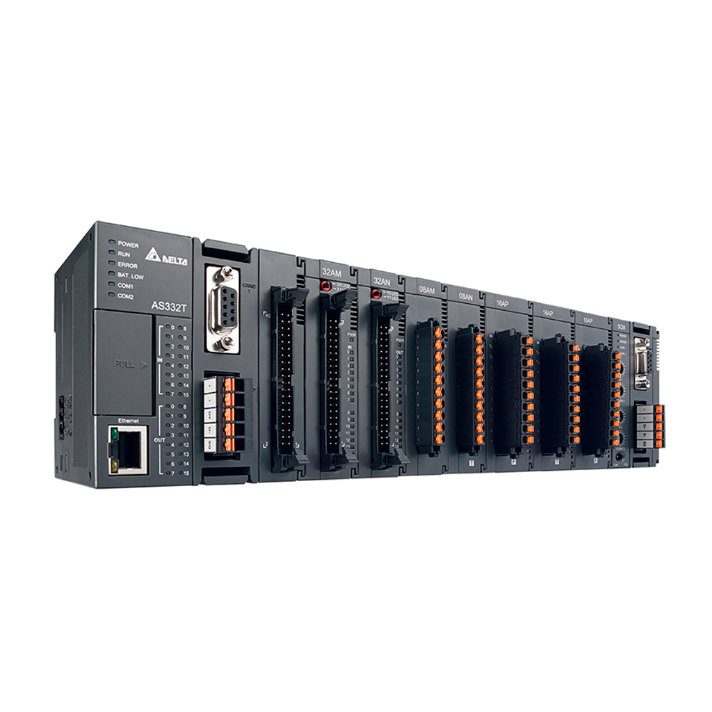
Functional cards (AS-F2AD and AS-F2DA)
Functional cards are available for the AS300 series. The AS-F2AD card has two inputs and AS-F2DA has two analog outputs.
For more information on the cards, see chapters 9.2.4 and 9.2.5 of the AS series module manual and the card installation manuals.
| Document Name | Description | Language | Issue Date | Doc. Code | Filet |
| AS Series Module Manual | Introducing module specifications, installation, setting, and troubleshooting | English | 2019/11/28 | AS-0249820-07 | |
| AS-F2AD AS-F2DA | AS analog input / output function cards | Multilanguage | 2016/03/25 | 5014035400 |
1. Within ISPSoft, open HWCONFIG in the project manager.
2. After opening HWCONFIG you have two options:
- Upload the previously changed hardware settings and make the new changes to the card.
- Do the SCAN, but in this case it is only recommended if the PLC does not have any previous configuration, as the SCAN will identify all coupled hardware, but all will have factory settings.
3. If the PLC is offline, you can manually insert it by double-clicking on the card slot.
4. Now you must configure the reading or writing mode of the channels (voltage / current).
- Select the [General] tab.
- Select [Function Card Setting] 1 or 2 according to the slot the card is in.
- Adjust the read and write modes, sampling time and card average.
5. After configuring the cards, download them.
6. To read or write to the card channels, move the values to the dedicated system registers.
As can be seen in the images above taken from the AS series modules manual, there are system (SR) records for each type of analog signal. For reading cards, AS-F2AD, these are the SR168 / 169 registers for channels 1 and 2 of the card in the first slot and SR170 / 171 for channels 1 and 2 of the card in the second slot.
For writing cards, AS-F2DA, these are SR172 / SR173 for channels 1 and 2 of the card in the first slot and SR174 / 175 for channels 1 and 2 of the card in the second slot.
Programming example:
Considering an AS-F2AD as the first card and an AS-F2DA as the second, the programming would be as follows:
As can be seen in the image taken from the manual, the digital values are:
For reading the value ranges from 0 to 4000 (0 - 10V) and 4 to 2000 (4 to 20mA).
For writing the value ranges from 0 to 4000 for both the 0 to 10V signal and 4 to 20mA.