Para comunicar qualquer dispositivo modbus serial (RS485) com o CLP da TP70P, é necessário configurar a comunicação na mesma faixa e utilizar de blocos para escrita e leitura, pode utilizar dois modos para efetuar a configuração da porta serial de comunicação.
Assista o vídeo passo a passo:
Abaixo um passo a passo:
- Movendo valores para memorias especificas de configuração da porta serial, como exemplo COM2 em rede modbus 485, com os parâmetros baud rate (9600), data bits (7), paridade (even), stop bit (1), ASCII e ID do CLP como 1.
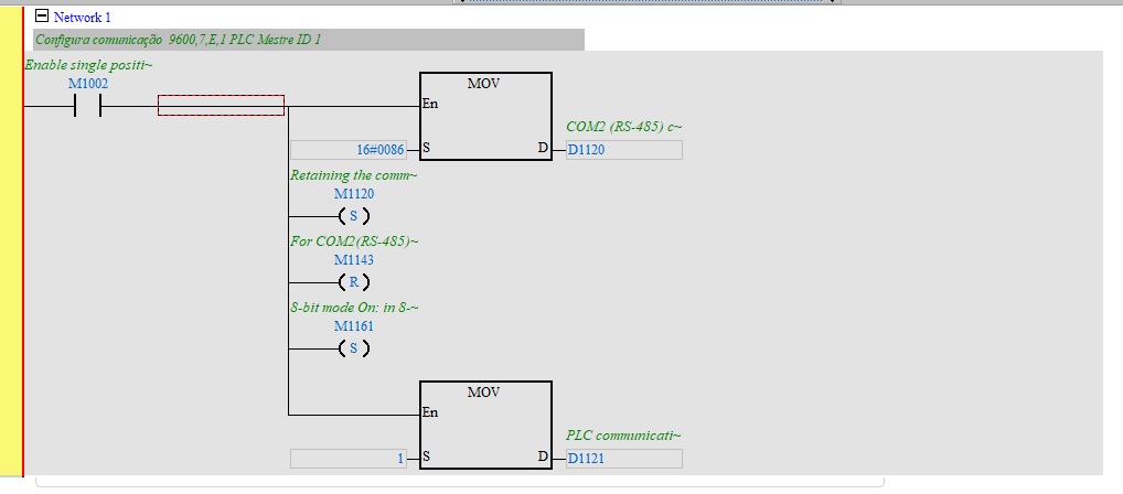
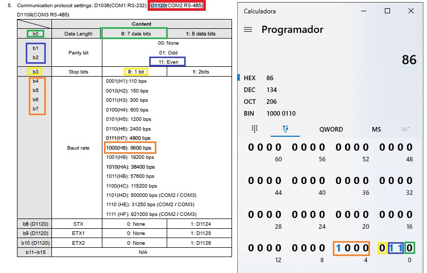
O valor do MOV na primeira linha de 16#0086 para a word D1120, está utilizando a sequência de bits demostrada na imagem abaixo, para configurar a porta COM2 em modbus RS485 como: 7, E, 1, 9600:
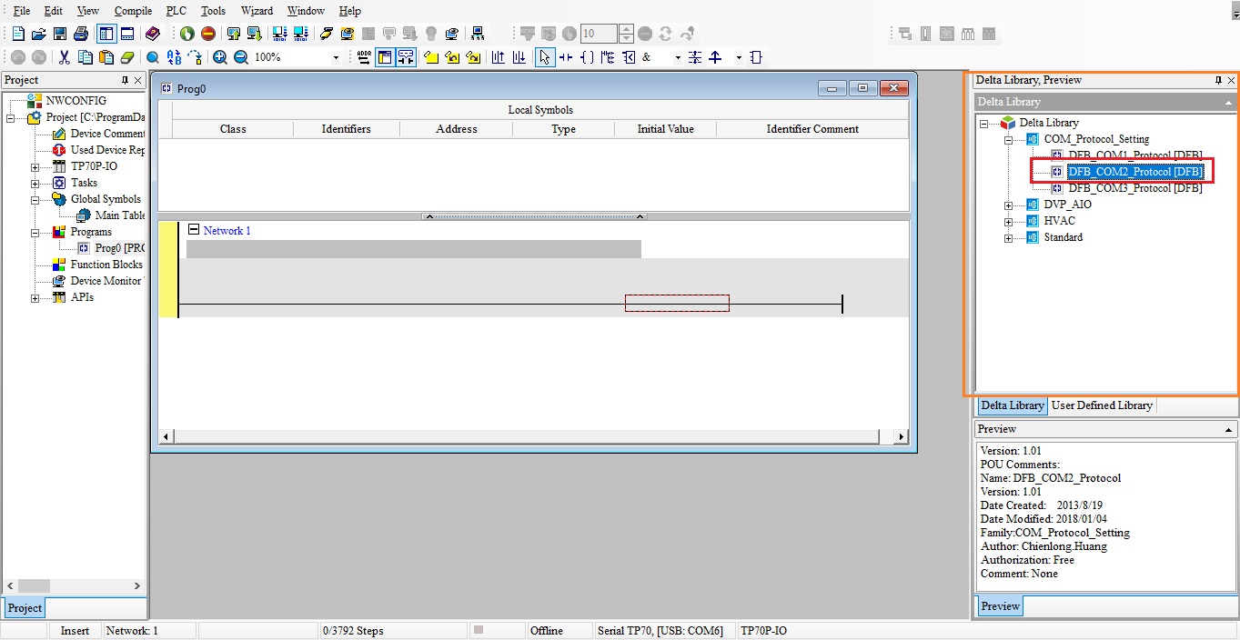
- Pode utilizar o bloco para definir a configuração da porta serial:
Selecionar a porta na biblioteca conforme demostra a imagem abaixo:
Arrastar para linha e configurar o bloco de acordo com a configuração da rede modbus, 9600/7/E/1 ASCII ID1:
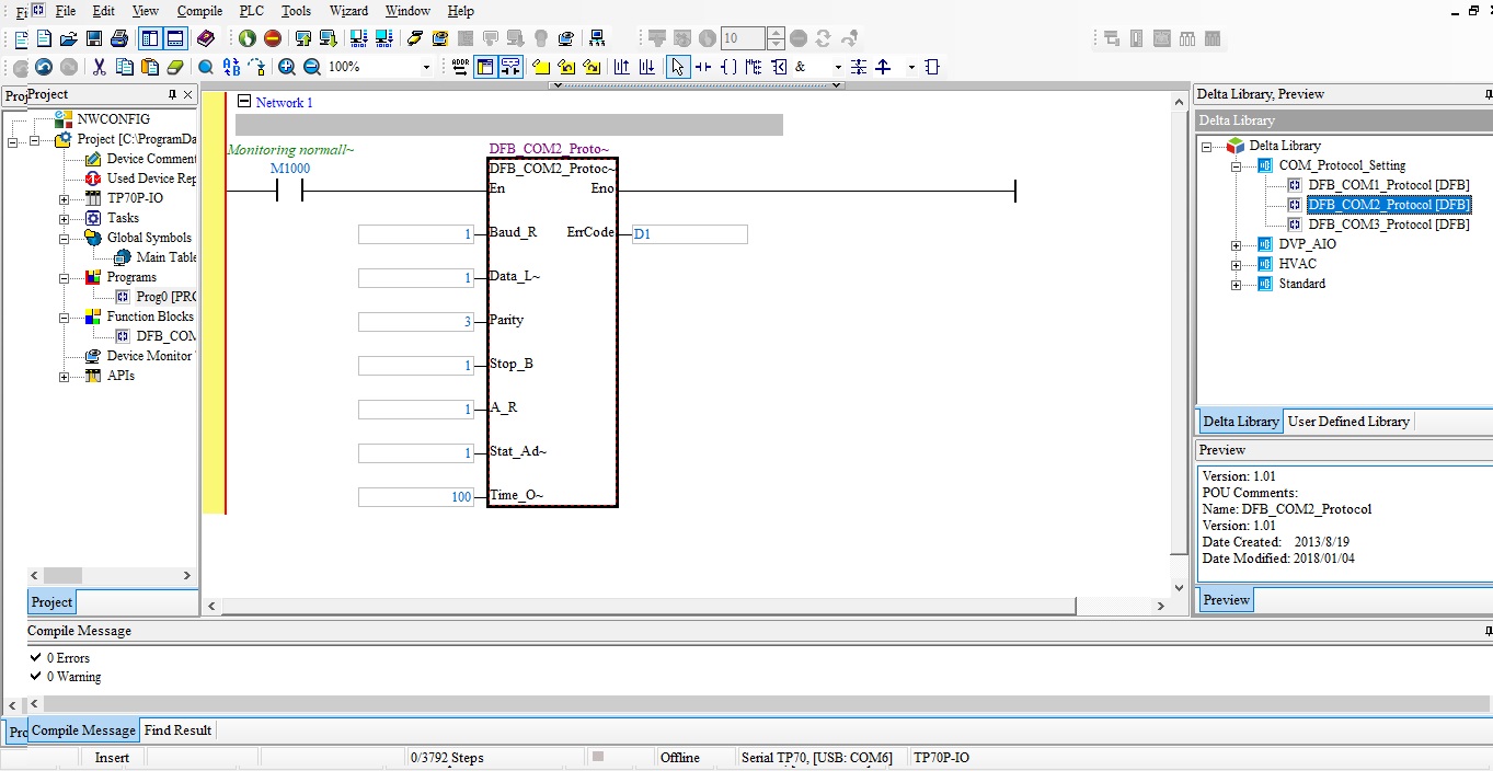
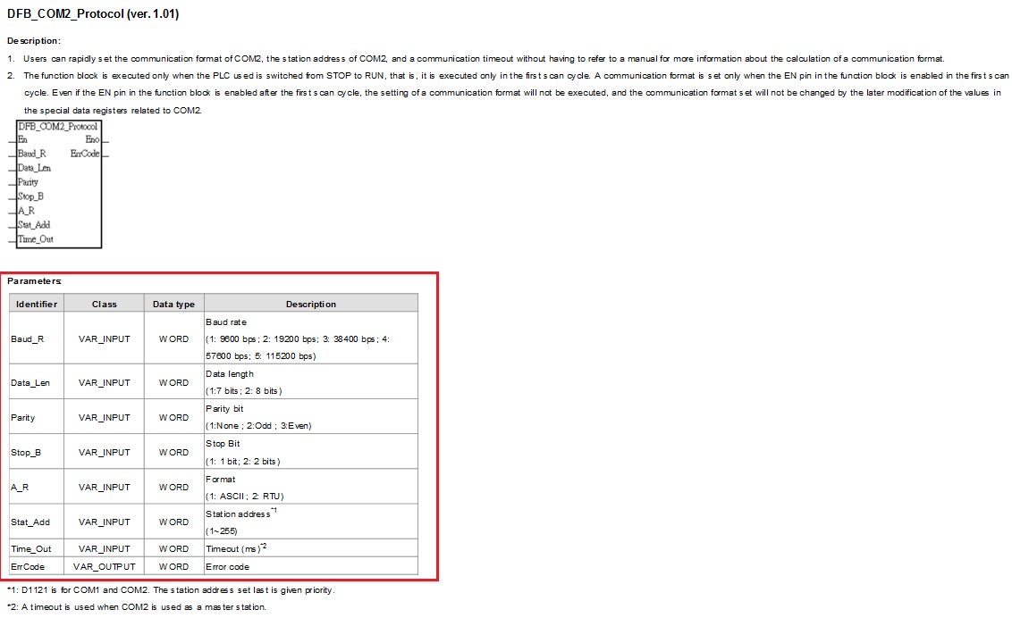
No help do bloco pode conferir os parâmetros de configuração:
Após configurado o protocolo deve utilizar bloco de escrita (MODWR) e bloco de leitura (MODRD) para enviar e ler dados na rede modbus, no entanto cada bloco deve ser acionado de maneira individual:
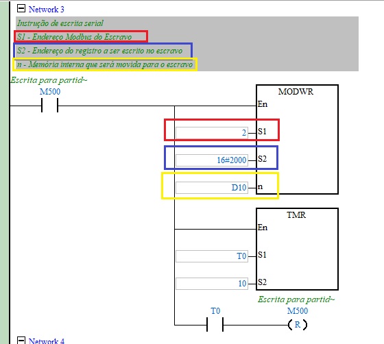
Exemplo utilizando bloco de escrita (MODWR) para enviar comando na word (2000h) do inversor MS300 de partida/parada/sentido de giro:
O bloco utilizado para leitura na rede modbus neste exemplo foi MODRD, conforme demostra o exemplo abaixo de leitura do inversor MS300 com a leitura na word (2100h):
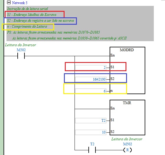
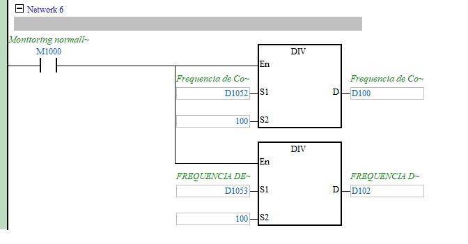
Ao efetuar a leitura utilizando o bloco MODRD os valores são armazenados nas word (D1050~D1055 ou D1070~D1085):
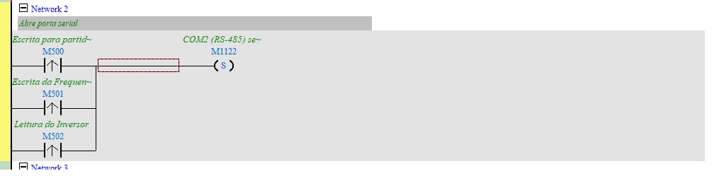
Após efetuar a leitura ou escrita é necessário acionar a memória M1122 para disparo da porta serial:
Para auxilio segue o link para baixar o exemplo do FAQ.
Clique aqui para baixar o exemplo -> Programa CLP MODRDeMODWR_TP70