Introduction
In this article we will present the step-by-step to communicate by electrical signals in pulse and direction the ASD-A2 sevo drive with the AS-300 PLC
Configuring the electrical connection of the ASD-A2 servo
The servo drive allows several forms of electrical connections, using an internal source (the servo drive's own power supply) or external source.
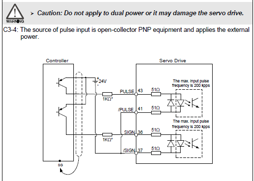
With electrical connection options in NPN or PNP.
Notes: The PNP connection must not exceed the maximum input voltage of the Drive of 5 VDC.
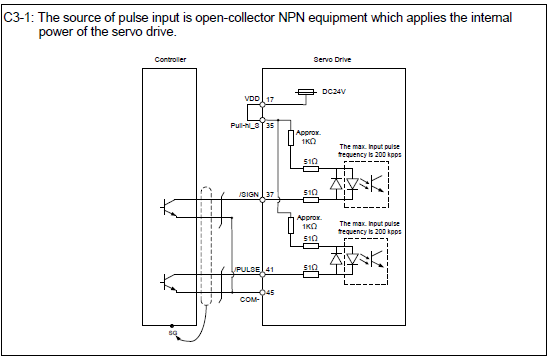
1 - Connection in NPN using internal source.
2 - PNP connection using internal source.
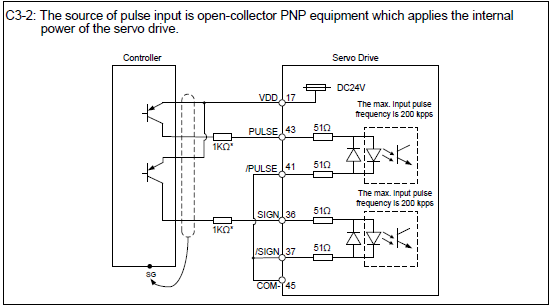
Note: When using the PNP connection with an internal source, it is necessary to use 1KΩ resistors.
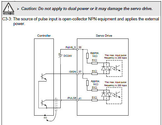
3 - Connection in NPN using external source, be careful not to use the internal source of the drive when selecting the option of connection with external source.
4 - PNP connection using external source, be careful not to use the internal source of the drive when selecting the option of connection with external source.
Note: When using the PNP connection with an external source, it is necessary to use 1KΩ resistors.
Configuring the ASD-A2 parameters
Adjust the parameters below:
5- Set the parameter P2-08 = 10 to restore the factory settings.
6 - Turn the servo off and on again.
7 - Set P1-01 = 0000 (PT mode).
8- Set P1-44 = 1.280.000 this parameter is responsible for the maximum resolution of pulses per vote of the servo drive, we define this value to represent the maximum resolution of the servo drive.
9- Set P1-45 = 1,000 we set this value to represent the resolution of the number of pulses around the servo drive. This value is only representative for the example below.
10 - Turn the servo off and on again.
Programming the AS300
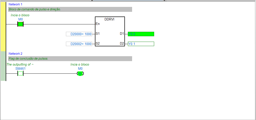
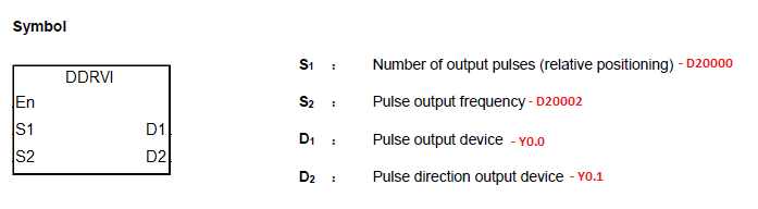
1 - To use the AS programming, regardless of the form of the electrical connection of the sevo, you can use the DDRVI block.
The DDRVI block is the incremental pulse command
Block functionality:
Input S1 represents the number of pulses per revolution that will be sent from the PLC AS-300 to the servo. Example with the decoupled servo - In parameter P1.45 the value 1000 was inserted for a complete resolution of the servo motor (360º), in input S1 of the AS-300 the value was entered in word D20000 = 1000 then the PLC will give the command 1000 pulses so the servo will make a complete turn (360º), if you need to make 5 complete turns on the servo the value in the word D20000 = 5000.
Input S2 is the AS-300 output pulse speed (Hz), in short it is the rotation speed of the servo, the higher the value entered in word D20002, the faster the speed of the servo drive, respecting the maximum speed of rotation of the servo drive and the maximum output frequency of the PLC. Example with the value in word D20002 = 1000 the servo drive will be a rotation of 60 RPM.
Output D1 represents the pulses that will be sent from the AS-300 (Y0.0) to the pulse input of the servo motor.
Output D2 is the direction (Y0.1) of the rotation of the servo motor, according to the value entered in input D1. Example - inserting the value D20000 = 1000 clockwise, if the value is negative the sevo will be counterclockwise.
Block definitions:
When disabling the memory or input at the beginning of the line (M0) the block is disabled and does not complete the output pulses, when starting again, the pulse count will start from 0.
The block provides information if the number of pulses sent from the PLC to the servo drive has been completed per output channel:
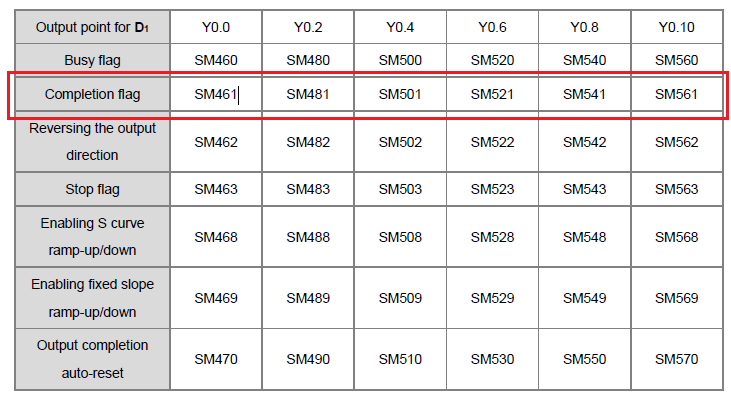
This information and other additional information of the block are provided in the manual, “Introducing devices and instructions ” pages 1055 to 1068.
For more information, see the AS series programming manual.
|
Product Name |
Description | Language | Issue Date |
Doc. Code |
|
ASD-A2 |
ASDA-A2 Series User Manual | English | 2019/09/21 | AT |
|
AS Series Programming Manual |
Introducing devices and instructions | English | 2019/06/21 |
AS-0249720-06 |