Introduction
This article will present the step by step to configure the analog inputs and outputs of the AS218 PLC.
Configuring analog channels
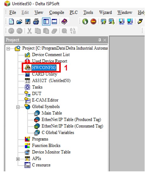
1. Within ISPSoft, open HWCONFIG in the project manager.
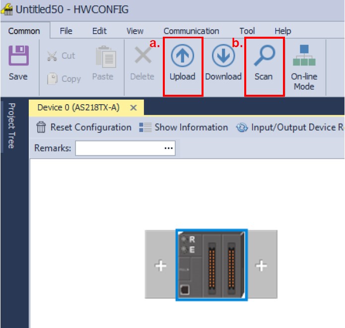
2. After opening HWCONFIG you have two options:
The. Upload the previously changed hardware settings and make the new changes to the card.
B. Do the SCAN, but in this case it is only recommended if the PLC does not have any previous configuration, as the SCAN will identify all coupled hardware, but all will have factory settings.
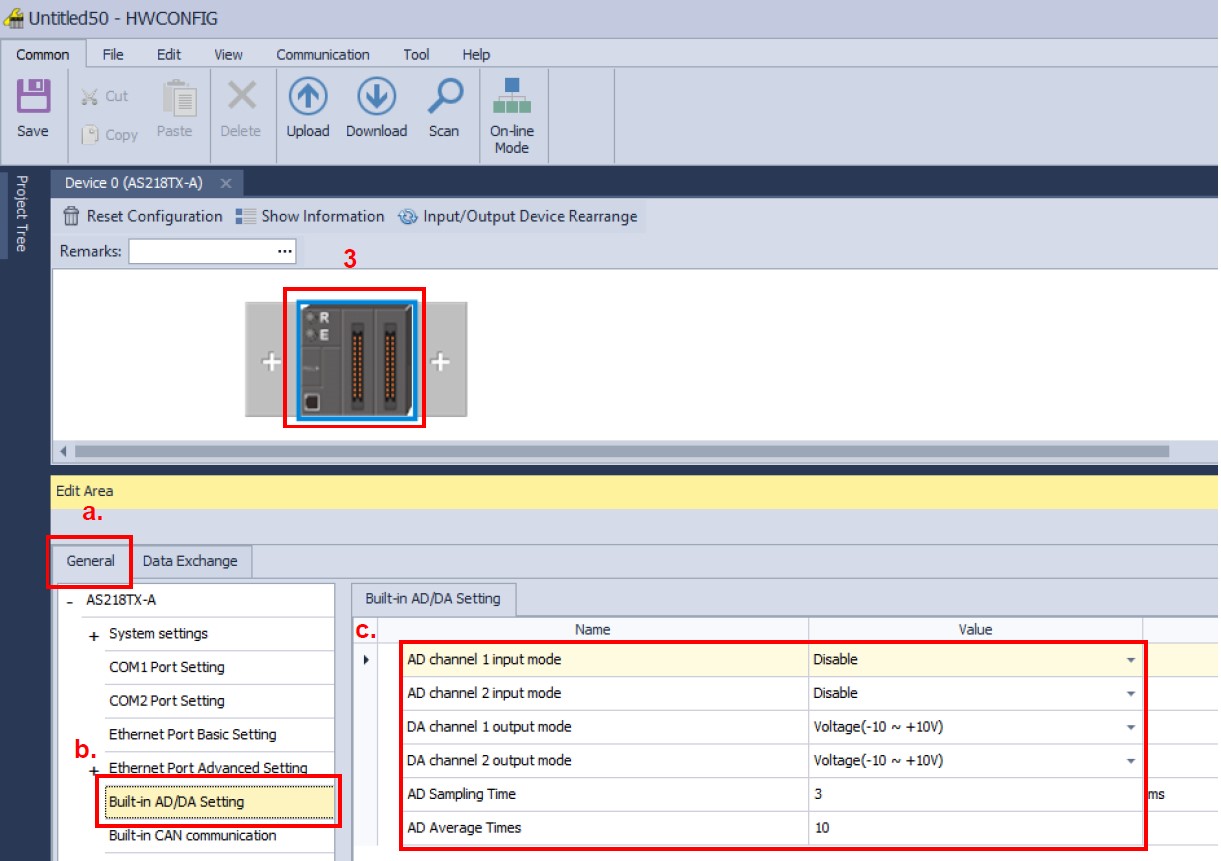
3. Select the AS218 CPU.
4. Now you must configure the reading or writing mode of the channels (voltage / current).
The. Select the [General] tab.
B. Then select the [Built-in AD / DA Setting]
ç. Configure the input and output operating modes.
Schedule
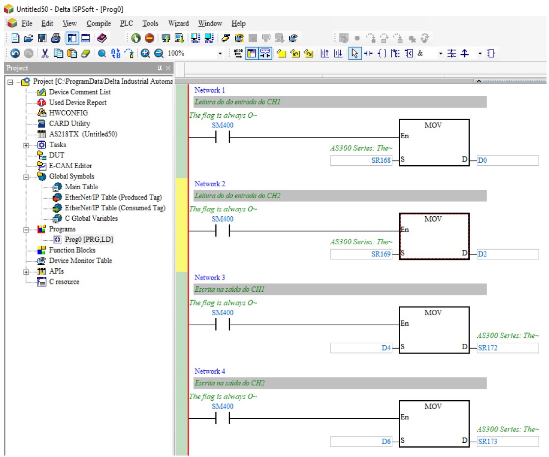
To read or write the analog channels, move values to the dedicated system registers.
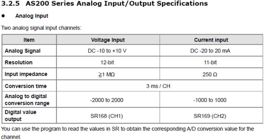
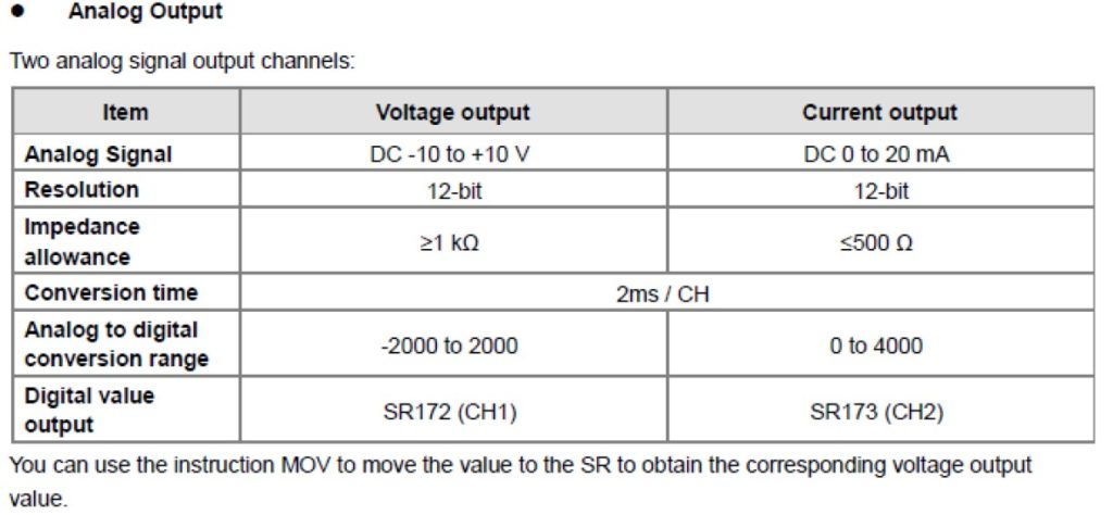
As can be seen in the images above taken from the AS series hardware manual, there are system (SR) records for each type of analog signal. To read channels 1 and 2 of the analog inputs use SR168 / 169 and to write the records SR172 / 173 in channels 1 and 2 of the analog outputs.
Programming example:
As it can be seen in the image taken from the manual that the digital values are:
- For reading the value ranges from -2000 to 2000 (-10 to + 10V) and -1000 to 1000 (-20 to 20mA).
- For writing the value ranges from -2000 to 2000 (-10 to + 10V) and 0 to 4000 (0 to 20mA).
For more information, refer to the AS series hardware and programming manual.
| Document Name | Description | Language | Issue Date | Doc. Code | Filet |
| AS Series Hardware Manual | Introducing hardware specifications, addressing, wiring, maintenance, and troubleshooting | English | 2018/09/10 | AS-0249520-05 | Link |
| AS Series Programming Manual | Introducing devices and instructions | English | 2019/06/21 | AS-0249720-06 | Link |